
Page 544 - APPLIED PROCESS DESIGN FOR CHEMICAL AND PETROCHEMICAL PLANTS, Volume 1, 3rd Edition
P. 544
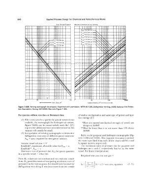
510                       Applied Process Design for Chemical and Petrochemical Plants

                                                   Vent Release Pressure   Maximum Pressure During  Venting
                                                                                11  1
                                                                          P,.d = 0.2 bar ga  --...
                                                                          P,ed ;;; 0.4 bar ga   -,.  ,"
                                                                          P,ed=0.6  bar ga  -
                                                                          Pied= 0.8 bar ga  --...  �  rs..."
                        �'                   c-Pstat�0.1  bar qa          P,00 = 1.0 bar ga  --...   I',:-,..   '   .......
                                                                                                              �-
                        '\" . �           /                               P,ed  = 1.5 bar ga  ---.,.  '""  I'\"   I'\ '\   ,/'  :;  v
                                                                                          I'-
                                          r.
                                             ir--  P,tat = 0 .2 bar ga
                                                                          P,od = zo bar ga
                           I\.  'i;  \.   //  ...--P,, •• �o.5 bar ga                   !"-..'  '   �   ,"'-.  /  II' .....
                                                                                           -, !'\.'
                                                                                                          /
                             '�       rt- /                                                -,  !'\.'  )A.  /  '/  � P'
                                         ,,  /
                                                                                               '
                               \.�   /V                                                     1,  "  '   �  � Po'   ..... ��
                                 ' �  �  ;                                                  ....,  .....   �  i/  )"
                                                                                            ..... �-
                                     "'�\.                                               ....,/  .,.  ...   �  �"'
                                                                                          �_,
                                      I\  '  �       ,_                               /"  '/      h
                                         '    --        - -- --  - --  - - --  p(,;     0       ; �   /
                                           �
                                                                                   IY/  �  ..... � ..
                                                                                ... �
                                          � �
                                           !   '�                           .........   �  /  � /
                                                                              .....
                                           I                             '/ v  ...   Vj  /  �
                                           I   ""'   ��                    v  '/ ��   �
                                           I                          /  /  ,;
                                           I                                     ;
                                                                         /'.'.
                                           I        "'"�            v/ �        ...  �   I
                                           I          \�            /h  v:   ..... �  ........   :
                                           :            '\�         ':/ �  t>       I
                                           I              \  �       ........:::  /'   I
                                           I                \."\  v                 :
                                           ;                  �                     I
                                           t                                        :
                       50         10                            0.1                10            100            1000
                                    ...,._      Vent  Area, rn 2                Vessel  Volume,  m'-----
                 Figure 7-638.  Venting nomograph  for propane.  Reprinted with pennission, NFPA 68-1988, Deflagration  Venting,  (1988)  National  Fire  Protec-
                 tion Association,  Quincy,  MA 02269.  See note Figure 7-63A.
                  For systems without test data or literature data     of similar configuration and same type ofignitor and igni-
                                                                       tion energy  [27]
                    (I) vVhen test data for a particular gas-air system is not
                       available,  the nornograph for hydrogen air system,   *Must  not exceed mechanical  strength  of vessel;  use
                       Figure 7-630, can  be conservatively used.  Ref.  [27]   design or MA,.\<'P.
                       reports the additional vent area determined in this   **Must  be  lower than x or not more  than  10%  above
                       manner will  usually be small.                       lYV\WP.
                    (2)  Interpolation of  existing nornographs to determine
                       deflagration vent area of different gas-air mixtures:   Refer to  the propane and hydrogen nomographs  (Fig-
                       Ang= area required for new gas or mixture.      ures 7-63B and 7-630). The required vent area to protect
                                                                       the vessel  specified from each  of the charts will be a  and
                    Assume vessel volume = V'                          b,  square meters,  respectively.
                    Establish", maximum allowable value for P  red  = x   The  maximum  rates of pressure  rise for propane and
                    Establish**,  Psiat  = y                           hydrogen  are  r and r',  respectively,  bar/sec  in  the  same
                    Maximum rate of pressure rise, Kc, for gas  in question   vessel. For linear interpolation:
                  in a specific vessel  =  z bar/sec.
                                                                          Required vent area for new gas  =
                  Note: Kc values are not constant and vary with test condi-
                  tions. Kc provides means of comparing maximum rates of     [       ]
                  pressure rise for various gases, but should only be used for   [a +   (t. - r)   ( b - a)]= vent area,  sq meters   (7- 7])
                                                                                 ,
                  deflagration vent sizing if test data comes from test vessels   (r  - r)