
Page 543 - APPLIED PROCESS DESIGN FOR CHEMICAL AND PETROCHEMICAL PLANTS, Volume 1, 3rd Edition
P. 543
Applied Process Design 509
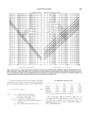
Vent Release Pressure Maximum Pressure During Venting
I
l
�
'I '
I\. r\. I\. P,ed = 0.2 bar ga ---._
I\ l\..\ ...
"' �,.. 1,--- P 5181 = 0.1 bar ga �
r--...'\.
v
��
"' �" "I\ v v:, i,,--P 5181 = 0.2 bar ga
� II.
i,,-- Pstat = 0.5 bar ga
II.
" �� v
I\
°"t\ �
"" 'r(\ l\..
'�'\.
'\... "\��
'
�\"
" r-. r-,.\
l'I 'I �II.
I '
i\ �
"
�
�\.'\
" v
50 10 0.1 10 100 1000
------Vent Area, m 2 Vessel Volume, m 3 ------< ...
Figure 7-63A. Venting nomograph for methane. Reprinteed with permission, NFPA 68-1988, Deflagration Venting, (1988) National Fire Pro-
tection Association, Quincy, MA 02269. Note: This material Is not the complete and official position of the National Fire Protection Associa-
tion on the referenced subject, which is represented only by the standard in its entirety. Note from this author: this statement applies to all
material referenced for use that originates with the National Fire Protection Association (27].
In order to calculate the same area results as the above *Coefficients/ exponents [27]
noted charts for methane, propane, coke gas, and hydro-
gen, the following equation is presented by NFPA-68 [27]: a b c d
Methane 0.105 0.770 1.230 -0.823
Propane 0.148 0.703 0.942 -0.671
(7-70) Coke Gas 0.150 0.693 1.380 -0.707
Hydrogen 0.279 0.680 0.755 -0.393
* Do not use for extrapolation beyond the nomographs.
when A,. = reguired vent area, sq meters
V = enclosure volume, cubic meters The nomographs (Figures 7-63A-D) apply for ves-
e = 2.718 (base natural Jog)
a, b, c, d = coefficients. see Table to follow sel/ equipment with length/diameter ratio (L/D) of 5 or
Pred = maximum pressure developed during vent- less, otherwise, a danger of detonation may exist. For
ing, bar ga. equipment with L/D > 5, refer to NFPA-68, Chapter 8
P,ta, = vent closure release pressure, bar ga. (27), and NFPA-69 [55].