
Page 545 - APPLIED PROCESS DESIGN FOR CHEMICAL AND PETROCHEMICAL PLANTS, Volume 1, 3rd Edition
P. 545
Applied Process Design 511
Vent Release Pressure Maximum Pressure During Venting
11 I I I
.,r--Pstat =0.1 bar ga P,ed = 0.2 bar ga -------. I �
-------. -,
/ ,--Pstat =0.2 bar ga
P,ed = 0.4 bar ga
.,
' ilv v / // ,-- P,tat = 0.5 bar ga P,ed = 0.6 bar ga -------. -, " � r.. / i.,,"" �� �
�""'
'
/.,
"
P,cd = 0.8 bar ga -------. <,
/
"\.[\
\ �
.... �
v
r.. '"'�
' \ .� \. / ..,., v P,ed = 1 .0 bar ga � <, ' "" // L,., i, ... �
��
'\ '\.'<..., � ii P,ed = 1 .5 bar ga -------. '" ' "'\ Y .. -: � � , ... ... �
r..
r..
'\.'� P,ed = 2.0 bar ga "'\ ," � "' ' .» � / vv ;�
r....-�
I
i..,
// I/I,,'
'\. ' � I <, r-, >"" r..,.. � /
i'i'I v �� :�/ ..-r
l'l.i'.. / ); /
� i\ v � .... '//
';
...
' � // � r- / ,.; �/
/ /
"
i\ �
�
" I\.\ l'-.. // ,.,.; /h -> / / ,.,.;
....
.,
.'\. '\.
'\
V/ /
/
;
...
v
; //
/
I "'\ / v v/ '/ / j I i
.,/ .... � �
'\ ,r-..
�
/
� v
' " �\ , /: , v" � , I I I
�' v..o: v v .,,,," l i .
�
' � v/
' " � v v !
�/
v
' "r'\. '\ I
I 'I\.'\.'\ v
I '\. '
i '
50 10 0.1 10 100 1000
----Vent Area, m 2 Vessel Volume, m 3 .,.
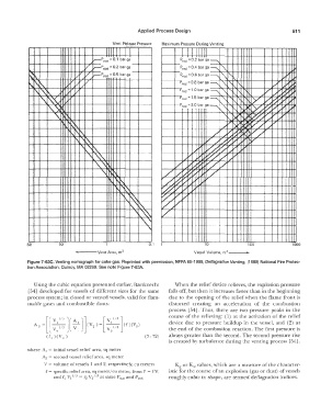
Figure 7-63C. Venting nomograph for coke gas. Reprinted with permission, NFPA 68-1988, Deflagration Venting, (1988) National Fire Protec-
tion Association, Quincy, MA 02269. See note Figure 7-63A.
Using the cubic equation presented earlier, Bartknecht When the relief device relieves, the explosion pressure
[54] developed for vessels of different sizes for the same falls off, but then it increases faster than in the beginning
process system; in closed or vented vessels, valid for flam- due to the opening of the relief when the flame front is
mable gases and combustible dusts: distorted creating an acceleration of the combustion
process [54]. Thus, there are two pressure peaks in the
course of the relieving: ( 1) at the activation of the relief
device due to pressure buildup in the vessel, and (2) at
the end of the combustion reaction. The first pressure is
always greater than the second. The second pressure rise
is created by turbulence during the venting process [54].
where A 1 = initial vessel relief area, sq meter
A2 = second vessel relief area, sq meter
V = volume of vessels 1 and 2, respectively, cu meters K" or Kst values, which are a measure of the character-
f = specific relief area, sq meter/ cu meter, from F = I V, istic for the course of an explosion (gas or dust) of vessels
and r, V, 113 = f2 \12113 at same P, 1 a 1 and P,ect roughly cubic in shape, are termed deflagratiou indices.