
Page 547 - APPLIED PROCESS DESIGN FOR CHEMICAL AND PETROCHEMICAL PLANTS, Volume 1, 3rd Edition
P. 547
Applied Process Design 513
• For small reiief areas, Pred > 1 bar, independent of for many specific dust types, and the same laws of flam-
ignition energy. Relief area (vent area, A) from mability apply as were previously presented for flammable
nomograms must be increased by a constant factor, gases/vapors, following the "cubic law" [27] for explosive
M == 0.08V 213. violence [54]:
Recommend applying only for methane, propane, and 113 1
solvent vapors due to insufficient data and for a static acti- (dp/dt)max,Vl (V1) = (dp/dt)ma.x, V2 (V2) 13, (7-73)
= Kc (gases), bar m/sec
vation pressure of the relief device of Pstat � 0.1 bar (see or K.t (dust), bar m/sec
reference [54]).
Vessels with internal components may be susceptible to (dp/dt)pr � d.Vl (Vi)l/3 = (dp/dt)pred,V2 (V2)1/3 (7-74)
turbulence in the gas mixture, which can lead to detona- = (Kc)pred or (K;,)Pred, bar m/sec
tions, which are not covered by this procedure. Hydrogen
is particularly vulnerable to detonations; therefore, for when subscript G = for gas systems
such systems, a specialized expert should be consulted. st = for dust system
The details of NFPA-68 should also be consulted as there f = specific relief area
are many factors that must be recognized. Also see refer- (dp/dt)ma., = maximum rate of pressure rise,
ence [34]. bar/sec
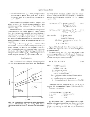
The range of the nomographs can be extrapolated or f1 (V;)1;3 = f2 (V2)1;3
extended for a specific vessel volume by cross-plotting as
shown in Figure 7-64, limiting to a constant Pred for each Figures 7-65A through H are the venting area require-
chart at varying Pstat· Do not extrapolate below Pstat of 0.05 ments for dust explosions. These are based on high ener-
bar ga, nor below P red of 0.1 bar ga. P red should not be gy ignition sources.
extrapolated above 2.0 bar ga; Pstat can be extrapolated but An equation from Ref. [27] represents the dust explo-
it must always be less than Pred by at least 0.05 bar [27]. sion nomographs, Figures 7-65A, B, and C. Because the
equation was derived from the nomographs, it is no more
Dust Explosions accurate but may be more convenient:
It has been somewhat of a surprise to many engineers (7-75)
that fine dust particles are combustible and will explode
where a = 0.000571 e<2) (Pstai)
2.0·��----------------- b = 0.978 e(-0.105) (Pstat)
c = -0.687 e(0.226) (Pstat)
Av = vent area, sq meters
V = enclosure volume, cu meters
e = 2.718, natural logarithm
Prcd = maximum pressure developed during venting,
bar ga.
Psi.at= vent closure release pressure, bar ga.
K,t = deflagration index for dust, bar m/sec., Table 7-28
Other equations are presented in Ref. (27] lo repre-
V= 10 m3 sent the dust nomographs of Figures 7-650 through 65H.
P,ed � 1 bar Reference conversions:
f-Do not
I extrapolate
I below 0.05 I - bar-meter/second= 47.6 psi-ft/sec
I bar ga = 0.021 bar-meter/sec
I l - psi-ft/sec = 1.01 bars
1 - atrn
Q I
0 0.'J5 0.4 o.a 1 - atrn = 1 4. 7 psi
pstat• bar ga
The dust hazard class, K,;,, vessel volume and strength,
Figure 7-64. Extrapolation of nomographs for gases. Reprinted with and the relieving pressure of the vent closure are the key
pennission, NFPA 68-1988, Deflagration Venting, (1988) National
Fire Protection Association, Quincy, MA 02269. See note Figure 7- components of the relief determination using the nomo-
63A. graphs [27]. Although stated by Ref. [27] to be non-exact