
Page 106 - Template Tesis UTM v2.0
P. 106
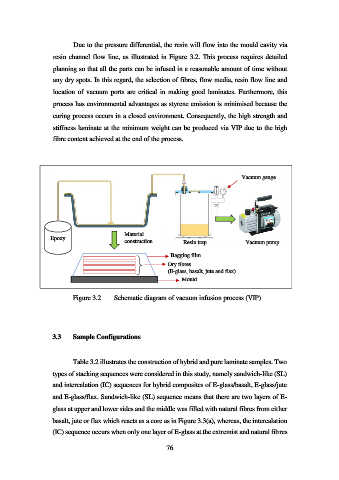
Due to the pressure differential, the resin will flow into the mould cavity via

                   resin channel  flow line, as illustrated in Figure 3.2. This process requires detailed
                   planning so that all the parts can be infused in a reasonable amount of time without

                   any dry spots. In this regard, the selection of fibres, flow media, resin flow line and
                   location  of  vacuum  ports  are  critical  in  making  good  laminates.  Furthermore,  this

                   process has environmental advantages as styrene emission is minimised because the
                   curing process occurs in a closed environment. Consequently, the high strength and

                   stiffness laminate at the minimum weight can be produced via VIP due to the high

                   fibre content achieved at the end of the process.


                                                                                     Vacuum gauge


                                            Material
                  Epoxy
                                            construction         Resin trap            Vacuum pump

                                                             Bagging film

                                                            Dry fibres
                                                            (E-glass, basalt, jute and flax)
                                                                Mould

                           Figure 3.2    Schematic diagram of vacuum infusion process (VIP)


                   3.3     Sample Configurations


                           Table 3.2 illustrates the construction of hybrid and pure laminate samples. Two

                   types of stacking sequences were considered in this study, namely sandwich-like (SL)

                   and intercalation (IC) sequences for hybrid composites of E-glass/basalt, E-glass/jute
                   and E-glass/flax. Sandwich-like (SL) sequence means that there are two layers of E-

                   glass at upper and lower sides and the middle was filled with natural fibres from either
                   basalt, jute or flax which reacts as a core as in Figure 3.3(a), whereas, the intercalation

                   (IC) sequence occurs when only one layer of E-glass at the extremist and natural fibres

                                                           76