
Page 111 - Template Tesis UTM v2.0
P. 111
This was done to suit the types of reinforcement and resin used. Prior to the test, all
the specimens were inspected to ensure all the cutting edges are in good conditions.
During the testing, specimens were aligned as perfectly as possible using the
recommended grip face, according to the sample thickness with the direction of the
pull. They were also tightened firmly to minimise the rotary motion that could induce
slippage. The gauge length was kept at 100 mm for all the specimens and for each of
the sample configuration, five measurements were tested to obtain an average result.
165 mm
57 mm
19 mm
13 mm
R 76 mm
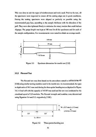
Figure 3.5 Specimen dimension for tensile test [125]
3.5.2 Flexural Test
The flexural test was done based on the procedures stated in ASTM D790-03
[126] using similar testing machine used in the tensile test. As recommended, the span
to depth ratio of 16:1 was used during the three-point bending test as depicted in Figure
3.6. A load cell with the capacity of 10 kN was used and the test was conducted at the
crosshead speed of 2.0 mm/min. The flexural strength and modulus were determined
using Equation 3.4 and 3.5, respectively [126] ;
W = 12.7 mm (t < 3.2 mm)
or
≤ L/4 (t > 3.2 mm)
L/2 L/2
L = 16 x t
Figure 3.6 Three-points bending test
81