Page 18 - Spotlight A+ Physics Form 4.5
P. 18

Form
                                                                                                          5
                                                                          Chapter 2 Pressure   Physics
                 SPM Clone
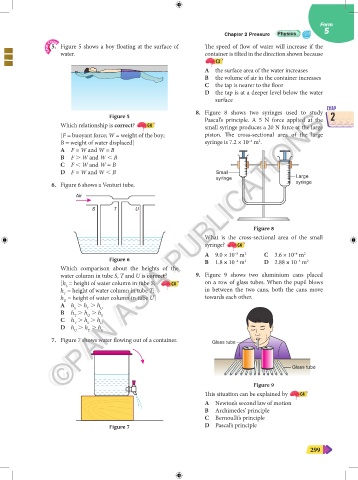
                   5.  Figure 5 shows a boy floating at the surface of   The speed of flow of water will increase if the
                     water.                                         container is tilted in the direction shown because
                                                                       C3
                                                                    A  the surface area of the water increases
                                                                    B  the volume of air in the container increases
                                                                    C  the tap is nearer to the floor
                                                                    D  the tap is at a deeper level below the water
                                                                       surface
                                                                                                           CHAP
                                                                  8.  Figure  8 shows two  syringes used to study
                     ©PAN ASIA PUBLICATIONS
                                     Figure 5                       Pascal’s principle. A 5 N force applied at the  2
                    ©PAN ASIA PUBLICATIONS
                     Which relationship is correct?   C4            small syringe produces a 20 N force at the large
                     [F = buoyant force; W = weight of the boy;     piston. The cross-sectional area of the large
                                                                                     2
                                                                                  –4
                     B = weight of water displaced]                 syringe is 7.2 × 10  m .
                     A  F = W and W = B
                     B  F . W and W , B
                     C  F , W and W = B
                     D  F = W and W , B                                Small
                                                                       syringe                   Large
                   6.  Figure 6 shows a Venturi tube.                                            syringe
                          Air

                               S      T      U


                                                                                    Figure 8
                                                                    What is the cross-sectional area of the small
                                                                    syringe?   C4
                                                                    A  9.0 × 10  m     C  3.6 × 10  m 2
                                                                                 2
                                                                             –5
                                                                                                 –4
                                     Figure 6                       B  1.8 × 10  m     D  2.88 × 10  m 2
                                                                                                  –3
                                                                                 2
                                                                             –4
                     Which comparison about the heights of the
                     water column in tube S, T and U is correct?     9.  Figure 9 shows two aluminium cans placed
                     [h  = height of water column in tube S;  C4    on a row of glass tubes. When the pupil blows
                      S
                     h  = height of water column in tube T;         in between the two cans, both the cans move
                      T
                     h  = height of water column in tube U]         towards each other.
                      U
                     A  h  . h  . h U
                         S
                             T
                     B  h  . h  . h S
                             U
                         T
                     C  h  . h  . h U
                         T
                             S
                     D  h  . h  . h
                         U    T   S
                   7.  Figure 7 shows water flowing out of a container.  Glass tube
                                                                                                Glass tube
                                                                                    Figure 9
                                                                    This situation can be explained by   C4
                                                                    A  Newton’s second law of motion
                                                                    B  Archimedes’ principle
                                                                    C  Bernoulli’s principle
                                     Figure 7                       D  Pascal’s principle


                                                                                                      299
   13   14   15   16   17   18   19   20   21   22   23