
Page 187 - Towards Trustworthy Elections New Directions in Electronic Voting by Ed Gerck (auth.), David Chaum, Markus Jakobsson, Ronald L. Rivest, Peter Y. A. Ryan, Josh Benaloh, Miroslaw Kutylowski, Ben Adida ( (z-lib.org (1)
P. 187
On Optical Mark-Sense Scanning
179
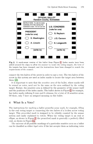
Fig. 2. A mark-sense version of the ballot from Figure 1. Index marks have been
added around the edges to allow the scanner to locate the voting targets, the form of
the targets has been changed, and the instructions have been changed to match the
requirements of the scanner.
connect the two halves of the arrow in order to cast a vote. The two halves of the
arrow in this system are used as index marks to locate the target area between
them [39].
It is important to note that the sensitive area of the ballot, where marks will
be sensed as votes, need not be the same as the area outlined by the voting
target. Rather, the sensitive area is defined by the geometry of the sensor itself
and the positions of the index marks. The ballot shown in Figure 2, for example,
has index marks defining 8 rows and 6 columns, for a total of 48 sensitive areas.
Of these, only 7 have an assigned meaning on this ballot.
4 What Is a Vote?
The instructions for marking a ballot prescribe some mark, for example, filling
in the oval voting target or connecting the two halves of a broken arrow voting
target. This prescribed mark is designed to be reliably counted by the sensor
system and easily explained to voters. When the voting target is an oval or
ellipse, as shown in Figure 2, the prescribed mark is generally a perfectly filled
oval, as shown in Figure 3a.
The universe of all possible markings of a particular sensitive area on a ballot
canbe classifiedas either legal votes if the law accepts them as indicating votes