
Page 190 - Towards Trustworthy Elections New Directions in Electronic Voting by Ed Gerck (auth.), David Chaum, Markus Jakobsson, Ronald L. Rivest, Peter Y. A. Ryan, Josh Benaloh, Miroslaw Kutylowski, Ben Adida ( (z-lib.org (1)
P. 190
D.W. Jones
182
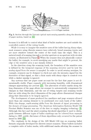
Fig. 5. Section through the Votronic optical mark-sensing assembly along the direction
of paper motion, based on [31]
because it is difficult to control what kind of ballot markers are used outside the
controlled context of the voting booth.
While it is easy to imagine the sensitive area of the ballot having sharp edges,
most scanners using discrete sensors have relatively broad scanning tracks and
are more sensitive toward the center of the track than the edges. This is a
natural result of scanning through a circular aperture or an aperture with circular
corners, as illustrated in Figure 5. When the scanner does not physically contact
the ballot, for example, to avoid smudging any marks that might be present, the
edge of the sensitive area is not sharply defined.
In the direction along the scanning track, the boundary of the sensitive area
is defined by the temporal response of the scanning circuitry and by how the
analog signal from the sensor is sampled. In order to avoid sensing smudges, for
example, scanners can be designed to check not only the intensity signal but the
derivative of that signal, so that a faint mark with sharp edges is counted even
while a darker smudge is ignored.
Any systems that use paper must account for the fact that paper is not di-
mensionally stable. Paper expands with increasing humidity, with dimensional
changes approaching one percent [27]. The placement of index marks along the
long dimension of the page allows the scanner to automatically compensate for
changes in that dimension, and the use of voting targets and scanning tracks
that are wide along the short dimension of the page allows dimensional changes
along that dimension to be largely ignored.
The development of mass produced fax machines and page scanners allowed
more than one sensing element to be positioned over each track of the ballot.
With this change, mark-sensing shifts from the domain of signal processing to
the domain of image processing. The American Information Systems Model 100
Precinct Ballot Scanner was one of the first to employ imaging technology [1].
Although this fact and the pixel-counting threshold algorithm it used to distin-
guish between different types of ballot markings can be inferred from manuals
dating to 1997, public disclosure of these algorithms only occurred in the patent
issued in 2005 [22].
The emphasis in the design of the AIS Model 100 was on scanning ballot
formats originally developed for discrete-sensor scanners. These ballots included
a complete suite of index marks, with additional marks allowing the scanner to