Page 33 - Dometic RM Series Refrigerators Service Manual
P. 33

33


                        THERMOSTAT REPLACEMENT

                        To replace the thermos tat, remove capillary from its clamp on the fresh food
                        evaporator fins, Remove the two sealing plugs, one on the outside and one on the
                        inside of the cabinet. Straighten the capillary and pull it through the cabinet,
                        Remove the thermostat by mscrewing         it from the gas filter and the flame failure
                        safety device.

                        NOTE :  Always, shut off the gas supply before removing any gas part from the
                                refrigerator,


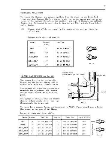
                                By-pass screw sizes and part No.

                                        1       By-pass         Part No.
                                                  screw

                                                   14            34 19

                                                                 17 28
                                 RM46                            17 28

                                                   s17           17 28
                                                                                                    Fig. 54
                                                   s17          17 28


                                                                             couple
                                                                                      into flame)
                            THE GAS BURNER (see fig.
                       The burner has the jet horizontally
                        located and the burner mixing tube is
                        formed as a bend with vertical outlet.

                       The            air inlets are pre-set and
                        therefore not adjustable. The burner
                        and the burner holder are made in one
                        piece.

                        The burner is provided with the
                       electric failure safety device and the
                        thermocouple tip is pre-set.                                       Fig. 55

                        To check for a correct flame, set thermostat to               Flame should have a bright
                       blue crown at the base of the

                        Burner jet sizes and input

                          Mode   Butane       Part           Propane      Part           Input BTU/h

                        RM24        24     289 00               24                           600
                                    34     200 26               43          26              1000
                                    43     200 26               51     200 26               1100
                                    51     200 26               52     200 36               1200

                                    5 1    200 26               53     200                  1360
   28   29   30   31   32   33   34   35   36   37   38