
Page 166 - REPOWER REFERENCE GUIDE (2020)
P. 166
Corrosion Protection
If the boat is to be equipped with underwater metal accessories (i.e. stainless steel tie bar, trim tabs, etc.) that are
interconnected with the sterndrive, these components must be equipped with their own corrosion protection devices, and must
not rely on the sterndrive for corrosion protection. Failure to do this could overload the sterndrive's corrosion protection system,
resulting in corrosion damage to both the sterndrive and the other underwater accessories. In the case of trim tabs (after
planes), the ABYC standards allow for the trim tabs to be isolated from the boat's cathodic bonding system to reduce the load
on the boats protection system. Refer to the ABYC standards for more details, as well as the accessory manufacturer's
installation instructions.
Testing Procedure for Corrosion Protection
Refer to Marine Corrosion Protection Guide (90‑881813 02) for further explanation of the testing procedures.
IMPORTANT: If the unit is equipped with a MerCathode System, make sure the battery is fully charged (12.6 volts or above).
IMPORTANT: New boats will usually produce higher readings than normal. This is because the drive unit is being protected by
a new finish and new sacrificial anodes. To obtain an accurate diagnosis, the test should be performed after the boat has been
used for at least one or two weeks. This will give the paint a chance to "soak" and acquire minor abrasions and scratches,
which will result in a more accurate reading.
IMPORTANT: Boats should be moored (without being operated or disturbed) for at least eight hours before performing the test.
This is necessary to allow the MerCathode System and sacrificial anodes to polarize the water molecules in direct contact with
the drive. Be careful not to rock the boat excessively while boarding to perform the test, as this will alter the test readings.
1. Unplug shore power, if equipped.
2. Measure hull potential with the silver/silver chloride reference electrode and digital volt/ohmmeter.
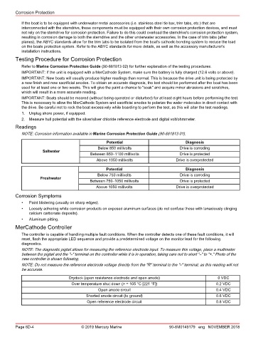
Readings
NOTE: Corrosion information available in Marine Corrosion Protection Guide (90‑881813 01).
Potential Diagnosis
Below 850 millivolts Drive is corroding
Saltwater
Between 850–1100 millivolts Drive is protected
Above 1050 millivolts Drive is overprotected
Potential Diagnosis
Below 750 millivolts Drive is corroding
Freshwater
Between 750–1050 millivolts Drive is protected
Above 1050 millivolts Drive is overprotected
Corrosion Symptoms
• Paint blistering (usually on sharp edges).
• Loosely adhering white corrosion products on exposed aluminum surfaces (do not confuse these with tenaciously clinging
calcium carbonate deposits).
• Aluminum pitting.
MerCathode Controller
The controller is capable of handling multiple fault conditions. When the controller detects one of these fault conditions, it will
reset, flash the appropriate LED sequence and provide a predetermined voltage on the monitor lead for the following
diagnostics.
NOTE: The diagnostic pigtail allows for measuring the reference electrode input. To measure this voltage, place a multimeter
between the pigtail and the "–" terminal on the controller while it is in operation, taking care not to short "–" to "+." Photo of the
new controller is shown following.
NOTE: Do not measure the reference electrode voltage directly from the "R" terminal to the "–" terminal, as this reading will not
be accurate.
Drydock (open resistance electrode and open anode) 0 VDC
Over temperature shut down (> = 105 °C [221 °F]) 0.2 VDC
Open anode circuit 0.4 VDC
Shorted anode circuit (to ground) 0.6 VDC
Open reference electrode circuit 0.8 VDC
Page 6D-4 © 2019 Mercury Marine 90-8M0149179 eng NOVEMBER 2018