
Page 302 - REPOWER REFERENCE GUIDE (2020)
P. 302
Engine Alignment
b. Remove the rear engine mounting bolts and hardware.
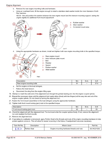
c. Using an overhead hoist, lift the engine enough to install a stainless steel washer inside the inner diameter of both
fiber washers.
NOTE: This will position the washer between the new engine mount and the transom mounting support, raising the
engine slightly for additional front mount adjustment.
a - Rubber washer
a b - Steel washer
c c - Corrected mount area
b
68277
d. Using the appropriate hardware as shown, install and tighten both rear engine mounting bolts to the specified torque.
c a - Rear engine mount
d b - Inner transom plate mount
c - Bolt
d - Washer
a e e - Spacer
f - Rubber washer
g - Steel washer
g
f
b 7941
Description Nm lb‑in. lb‑ft
Rear engine mounting bolts 51 – 37.6
e. Set the engine on the boat stringers.
f. Relieve the hoist tension.
g. Disconnect the sling from the engine lifting eyes.
19. Attempt to insert the solid end of the alignment tool through the gimbal bearing and into the engine coupler splines.
20. Repeat the necessary steps until the alignment tool easily slides (freely with two fingers) all the way into and out of the
engine coupler splines. Do not check by turning the alignment tool.
21. Fasten the front mount assemblies to the boat stringers using the appropriate hardware.
22. Tighten both front mount locking (jam) nuts to the specified torque.
Description Nm lb‑in. lb‑ft
Front mount locking (jam) nuts 80 – 59
23. Check the alignment with the alignment tool. The tool must enter the coupler splines freely. If not, remove the alignment
tool and readjust the front mounts.
24. Remove the alignment tool.
25. If operating in a saltwater environment, apply Perfect Seal to the threads and nuts of the engine mounting hardware to help
protect against corrosion. This will allow for easier loosening in the future, if readjustment becomes necessary.
Tube Ref No. Description Where Used Part No.
19 Perfect Seal Engine mounting hardware threads and nuts 92-34227Q02
Page 8D-14 © 2019 Mercury Marine 90-8M0149179 eng NOVEMBER 2018