
Page 306 - REPOWER REFERENCE GUIDE (2020)
P. 306
Engine Alignment
• Align the engine to position the pilot on the propeller shaft coupler into the recess in the transmission output flange so that
the mating surfaces of the flange and the coupler are parallel within 0.07 mm (0.003 in.).
7534
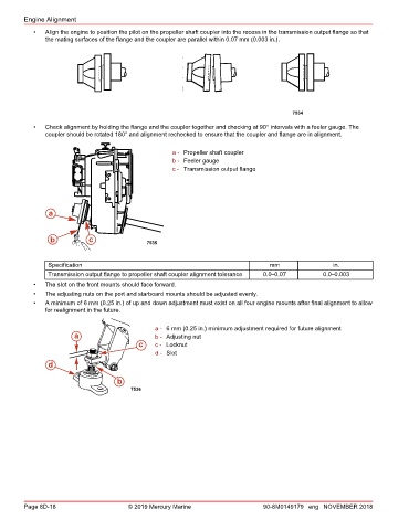
• Check alignment by holding the flange and the coupler together and checking at 90° intervals with a feeler gauge. The
coupler should be rotated 180° and alignment rechecked to ensure that the coupler and flange are in alignment.
a - Propeller shaft coupler
b - Feeler gauge
c - Transmission output flange
a
b c 7535
Specification mm in.
Transmission output flange to propeller shaft coupler alignment tolerance 0.0–0.07 0.0–0.003
• The slot on the front mounts should face forward.
• The adjusting nuts on the port and starboard mounts should be adjusted evenly.
• A minimum of 6 mm (0.25 in.) of up and down adjustment must exist on all four engine mounts after final alignment to allow
for realignment in the future.
a - 6 mm (0.25 in.) minimum adjustment required for future alignment
a b - Adjusting nut
c c - Locknut
d - Slot
d
b
7536
Page 8D-18 © 2019 Mercury Marine 90-8M0149179 eng NOVEMBER 2018