
Page 305 - REPOWER REFERENCE GUIDE (2020)
P. 305
Engine Alignment
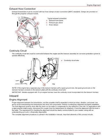
Exhaust Hose Connection
Exhaust hoses/tubes must be secured with two hose clamps at each connection (ABYC standard). Clamps are provided on
through‑the‑propeller exhaust models.
a Typical exhaust connection
a - Exhaust hose (tube)
b b - Exhaust pipe elbow
c - Hose clamps
c
c c
b
68092
Continuity Circuit
The continuity circuit wire must be connected between the engine and the transom assembly for corrosion protection system to
operate effectively.
a - Continuity circuit wire
a 7794
NOTE: If the engine has a separate plug in the transom harness with a spare ground wire, the spare ground wire on the
transom harness connects to the transom plate with the continuity circuit wire.
IMPORTANT: Models equipped with 14‑pin engine harness have the continuity circuit incorporated into the transom harness.
Inboard
Engine Alignment
Proper alignment between the transmission, and the propeller shaft is essential to minimize noise, vibration, and power loss
and to avoid overstressing the transmission and drive line components. Perform a preliminary alignment at engine installation.
The final alignment must be done after the boat is in the water to compensate for any deflection in the hull. On applications with
a rigid propeller shaft coupler, disconnect the coupler from the transmission for shipment. Check the alignment with the boat in
the water. The requirement for checking the alignment should be clearly communicated to your dealers, along with an
understanding as to who is financially responsible.
The complete alignment procedure is outlined in the installation manuals. Important elements of this process include:
90-8M0149179 eng NOVEMBER 2018 © 2019 Mercury Marine Page 8D-17