
Page 301 - REPOWER REFERENCE GUIDE (2020)
P. 301
Engine Alignment
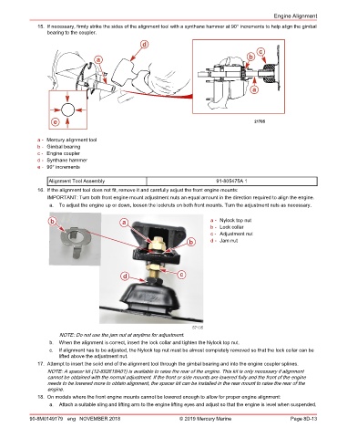
15. If necessary, firmly strike the sides of the alignment tool with a synthane hammer at 90° increments to help align the gimbal
bearing to the coupler.
d
c
a b
a
e 21705
a - Mercury alignment tool
b - Gimbal bearing
c - Engine coupler
d - Synthane hammer
e - 90° increments
Alignment Tool Assembly 91‑805475A 1
16. If the alignment tool does not fit, remove it and carefully adjust the front engine mounts:
IMPORTANT: Turn both front engine mount adjustment nuts an equal amount in the direction required to align the engine.
a. To adjust the engine up or down, loosen the locknuts on both front mounts. Turn the adjustment nuts as necessary.
b a a - Nylock top nut
b - Lock collar
c - Adjustment nut
b d - Jam nut
d c
57135
NOTE: Do not use the jam nut at anytime for adjustment.
b. When the alignment is correct, insert the lock collar and tighten the Nylock top nut.
c. If alignment has to be adjusted, the Nylock top nut must be almost completely removed so that the lock collar can be
lifted above the adjustment nut.
17. Attempt to insert the solid end of the alignment tool through the gimbal bearing and into the engine coupler splines.
NOTE: A spacer kit (12‑892619A01) is available to raise the rear of the engine. This kit is only necessary if alignment
cannot be obtained with the normal adjustment. If the front or side mounts are lowered fully and the front of the engine
needs to be lowered more to obtain alignment, the spacer kit can be installed in the rear mount to raise the rear of the
engine.
18. On models where the front engine mounts cannot be lowered enough to allow for proper engine alignment:
a. Attach a suitable sling and lifting arm to the engine lifting eyes and adjust so that the engine is level when suspended.
90-8M0149179 eng NOVEMBER 2018 © 2019 Mercury Marine Page 8D-13