
Page 78 - REPOWER REFERENCE GUIDE (2020)
P. 78
Inboard Transmission and Driveline
Gear Ratio Selection
The transmission gear ratio and propeller must provide the optimum match between the engine and the boat application. Gear
ratio and propeller selection are affected by numerous factors including engine horsepower, WOT RPM, hull design, propeller
clearance, boat weight, and other factors. Several computer programs are available to assist in analyzing all of these variables
and selecting the proper propeller and gear ratio. Typically, a higher reduction transmission coupled with a slower turning,
larger diameter propeller provides the best efficiency for larger, heavier boats. Conversely, a lower reduction transmission and
a smaller diameter, faster turning propeller will generally provide superior performance on lighter, faster applications (35 mph
and above).
NOTE: If repowering with 75 HP or more step down the gear ratio. For example, if the boat had a 250 HP engine with 2.0:1
gear ratio and the replacement engine is 350 HP then consider using a 1.0:1 or 1.5:1 gear ratio with the new engine.
Typical Inboard Gear Ratios
Boat Length Gear Ratio
4.57–6.7 m (15–22 ft) 1.0:1
7–8.23 m (23–27 ft) 1.5:1
8.53–10.06 m (28–33 ft) 2.0:1
10.36–11.58 m (34–38 ft) 2.5:1
11.89–12.19 m (39–40 ft) 2.7:1
12.5–12.8 m (41–42 ft) 2.85:1
13.1–13.4 m (43–44 ft) 3.15:1
Engine and Propeller Shaft Installation Angle
Mount the transmission and engine so that the angle relative to horizontal is within the range shown on the installation
drawings. As a general rule, the propeller shaft angle should position a properly‑sized propeller at least one propeller diameter
below the waterline.
Installing the engine with the front end too high can cause aerate the transmission fluid and engine oil. Take special care on 5.7
MPI and 6.2 MPI V‑drive applications with propeller shaft angles of less than 9° to avoid water reversion problems through the
exhaust system. See Section 7 ‑ Exhaust System. The exhaust elbow outlets will have less than their prescribed amount of
downward slope with the exhaust elbows installed in their normal orientation. On these applications, reverse the exhaust
elbows to get the proper slope. The engine can be obtained from the factory with this orientation.
NOTE: 5.7 MPI, 6.2 MPI, and 8.1 model have an increased slope in the exhaust elbow outlets and can accommodate any
propeller shaft angle within the specified range in V‑Drive applications, without the need to reverse the elbow.
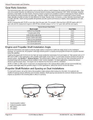
Propeller Shaft Rotation and Spacing on Dual Installations
For best performance, set up the boat so the propellers rotate outward when looking from the stern. As a general rule,
insufficient spacing reduces efficiency and increases vibration. Shaft spacing must provide the minimum distances between
engines as specified in the following table to allow for servicing.
a b
c d d c
14884
a - Inward propeller rotation
b - Outward propeller rotation
c - RH rotation
d - LH rotation
Page 4C-2 © 2019 Mercury Marine 90-8M0149179 eng NOVEMBER 2018