
Page 79 - REPOWER REFERENCE GUIDE (2020)
P. 79
Inboard Transmission and Driveline
Minimum Distance Between Engine Centerlines
Model Measurement
All Except 8.1 H.O. and Horizon 8.1 838 mm (33 in.)
8.1 H.O. and Horizon 8.1 927 mm (37.5 in.)
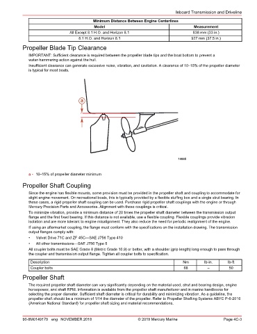
Propeller Blade Tip Clearance
IMPORTANT: Sufficient clearance is required between the propeller blade tips and the boat bottom to prevent a
water‑hammering action against the hull.
Insufficient clearance can generate excessive noise, vibration, and cavitation. A clearance of 10–15% of the propeller diameter
is typical for most boats.
a
14885
a - 10–15% of propeller diameter minimum
Propeller Shaft Coupling
Since the engine has flexible mounts, some provision must be provided in the propeller shaft and coupling to accommodate for
slight engine movement. On recreational boats, this is typically provided by a flexible stuffing box and a single strut bearing. In
these cases, a rigid propeller shaft coupling can be used. Purchase rigid propeller shaft couplings with the engine or through
Mercury Precision Parts and Accessories. Alignment with these couplings is critical.
To minimize vibration, provide a minimum distance of 20 times the propeller shaft diameter between the transmission output
flange and the first fixed bearing. If this distance is not available, use a flexible coupling. Flexible couplings provide vibration
isolation and are more tolerant to engine misalignment. They also reduce the need for periodic realignment of the engine.
If using an aftermarket coupling, the flange must conform with the specifications on the installation drawing. The transmission
output flanges comply with:
• Velvet Drive 71C and ZF 45C—SAE J756 Type 410
• All other transmissions—SAE J756 Type 5
All coupler bolts must be SAE Grade 8 (Metric Grade 10.9) or better, with a shoulder (grip length) long enough to pass through
the coupler and transmission output flange. Tighten all coupler bolts to specification.
Description Nm lb‑in. lb‑ft
Coupler bolts 68 – 50
Propeller Shaft
The required propeller shaft diameter can vary significantly depending on the material used, strut and bearing design, engine
horsepower, and shaft RPM. Information is available from the propeller shaft manufacturer and in marine handbooks for
selecting the proper diameter. Sufficient shaft diameter is critical for durability and minimizing vibration. As a guideline, the
propeller shaft should be a minimum of 1/14 the diameter of the propeller. Refer to Propeller Shafting Systems ABYC P‑6‑2016
(American National Standard) for propeller shaft sizing and material recommendations.
90-8M0149179 eng NOVEMBER 2018 © 2019 Mercury Marine Page 4C-3