
Page 89 - REPOWER REFERENCE GUIDE (2020)
P. 89
Engine Harness
• Additional accessory load up to 40 amps can be accommodated with an optional accessory harness/relay kit.
Applications
• Both MPI and carbureted engines received the new 14‑pin wiring harness.
• A new circuit breaker was introduced on the new engine wiring harness.
• The slave starter solenoid currently on carbureted engines has been replaced by a slave starter relay.
• Adapters for use with repower are available. If the adapters are used, SmartCraft would be handled by the traditional CAN
line (adapters are not for DTS).
Boat Harness Installation Guidelines—MPI Sterndrive
Boat Harness Connector to Engine
Select the boat harness by length.
Boat Harness and Key
Length of the Boat Switch Boat Harness
Harness Three Position (off/run/ (key switch is not included)
start)
61 cm (2 ft) 84‑896537 K02 84‑896537 A02
4.6 m (15 ft) 84‑896537 K15 84‑896537 A15
6.0 m (20 ft) 84‑896537 K20 84‑896537 A20
7.3 m (24 ft) 84‑896537 K24 84‑896537 A24
8.8 m (29 ft) 84‑896537 K29 84‑896537 A29
12.2 m (40 ft) 84‑896537 K40 84‑896537 A40
NOTE: Extension harnesses are available if longer length is needed.
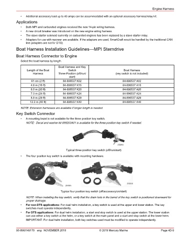
Key Switch Connector
• A mounting bezel is not available for the three position key switch.
NOTE: Decal and washer kit 899203A01 is available for the three position key switch if needed.
25046
Typical three position key switch (off/run/start)
• The four position key switch is available with mounting hardware.
25044
25045
Typical four position key switch (off/accessory/on/start)
NOTE: When installing the key switch, verify that the drain hole in the barrel of the key switch is positioned downward for
proper drainage.
• For non‑DTS applications: For dual helm installation, a key switch is used at the upper and lower station. The key
switches must operate independently.
• For DTS applications: For dual helm installation, a start and stop switch is used at the upper station. The lower station
can use either a key switch at the helm, or a key switch at the main panel and a start and stop switch at the lower helm.
IMPORTANT: For dual helm installation, both key switches used must be modified to operate independently.
90-8M0149179 eng NOVEMBER 2018 © 2019 Mercury Marine Page 4D-9