
Page 114 - Installation Manual - GenII DTS
P. 114
Accessories
7. Secure the harness within 46 cm (18 in.) of each end.
b
a
c
71148
a - From ERC handle trim switch
b - To ERC harness
c - Bullet connectors (to auxiliary trim switch)
Diagnostic Port
Diagnostic Port Installation
The diagnostic port provides an easy external access connection to the main engine (starboard engine for multi‑engine
applications) junction box for updating software, configuring the helm, and troubleshooting with the computer diagnostic system
(CDS) or CDS G3 SmartCraft diagnostic interface tool. The diagnostic port does not need to be mounted on the dashboard if
space is limited, but can be mounted under the dashboard, or in the cabin at an inconspicuous, but accessible location.
1. Identify the location where the diagnostic port will be installed. This location must be 1.5 m (5 ft) or less from the main
engine junction box at the helm.
NOTE: A 1.8 m (6 ft) 10‑pin yellow CAN data harness without resistors must be purchased separately to connect the main
engine junction box to the diagnostic port.
2. Ensure the area that will be cut out for the diagnostic port is clear of wires and obstructions, and has adequate clearance
behind the mounting bulkhead for the diagnostic port and CAN data harness. The CAN data harness when connected to
the diagnostic port must not have a radius bend less than 76.2 mm (3 in.) and must be secured with clamps or cable ties
within 25.4 cm (10 in.) of the connections.
3. If the mounting area is constructed of fiberglass, apply masking tape to the area to prevent chipping and cracking.
4. If the mounting area is vinyl covered, remove the vinyl with a razor blade to prevent the vinyl from tearing.
5. Cut out a 52 mm (2.125 in.) hole. Ensure the opening is free of sharp edges.
6. Verify the gasket is on the diagnostic port assembly and insert the assembly into the hole. Secure the diagnostic port
assembly with the retaining nut.
7. Connect the 10‑pin yellow CAN data harness to the main engine junction box and to the diagnostic port. Secure the data
harness with clamps or cable ties.
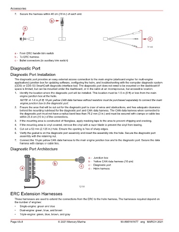
Diagnostic Port Architecture
a - Junction box
b - Yellow CAN data harness (10‑pin)
b c - Diagnostic port
a c d - Helm harness
d
72193
ERC Extension Harnesses
These harnesses are used to extend the connections from the ERC to the helm harness. The harnesses required depend on
the number of engines:
• Single‑engine: green and blue
• Dual‑engine: green, blue, and brown
• Triple‑engine: green, blue, brown, and gray
Page 4A-8 © 2021 Mercury Marine 90-8M0161677 eng MARCH 2021