
Page 116 - Installation Manual - GenII DTS
P. 116
Accessories
Foot Throttle
Required Mounting Clearances for the Foot Throttle
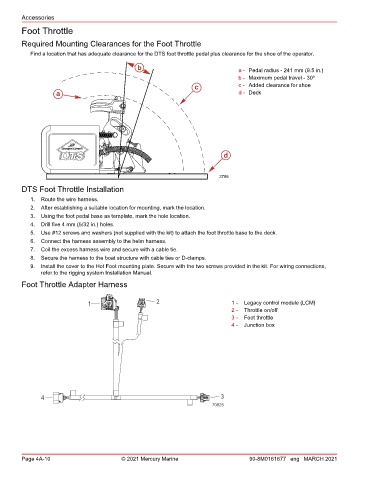
Find a location that has adequate clearance for the DTS foot throttle pedal plus clearance for the shoe of the operator.
b a - Pedal radius ‑ 241 mm (9.5 in.)
b - Maximum pedal travel ‑ 30º
c c - Added clearance for shoe
a d - Deck
d
3786
DTS Foot Throttle Installation
1. Route the wire harness.
2. After establishing a suitable location for mounting, mark the location.
3. Using the foot pedal base as template, mark the hole location.
4. Drill five 4 mm (5/32 in.) holes.
5. Use #12 screws and washers (not supplied with the kit) to attach the foot throttle base to the deck.
6. Connect the harness assembly to the helm harness.
7. Coil the excess harness wire and secure with a cable tie.
8. Secure the harness to the boat structure with cable ties or D‑clamps.
9. Install the cover to the Hot Foot mounting plate. Secure with the two screws provided in the kit. For wiring connections,
refer to the rigging system Installation Manual.
Foot Throttle Adapter Harness
1 2 1 - Legacy control module (LCM)
2 - Throttle on/off
3 - Foot throttle
4 - Junction box
4 3
70825
Page 4A-10 © 2021 Mercury Marine 90-8M0161677 eng MARCH 2021