
Page 117 - Installation Manual - GenII DTS
P. 117
Accessories
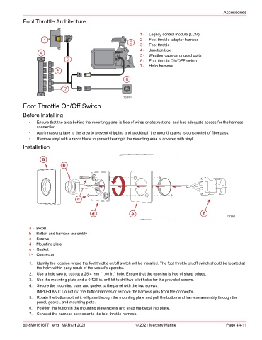
Foot Throttle Architecture
1 - Legacy control module (LCM)
1 LCM 2 - Foot throttle adapter harness
3 3 - Foot throttle
4 - Junction box
4 5 - Weather caps on unused ports
2 6 - Foot throttle ON/OFF switch
7 - Helm harness
5
6
7 THROTTLE
HAND
72194
Foot Throttle On/Off Switch
Before Installing
• Ensure that the area behind the mounting panel is free of wires or obstructions, and has adequate access for the harness
connection.
• Apply masking tape to the area to prevent chipping and cracking if the mounting area is constructed of fiberglass.
• Remove vinyl with a razor blade to prevent tearing if the mounting area is covered with vinyl.
Installation
a
b
c
d e f
70396
a - Bezel
b - Button and harness assembly
c - Screws
d - Mounting plate
e - Gasket
f - Connector
1. Identify the location where the foot throttle on/off switch will be installed. The foot throttle on/off switch should be located at
the helm within easy reach of the vessel's operator.
2. Use a hole saw to cut out a 25.4 mm (1.00 in.) hole. Ensure that the opening is free of sharp edges.
3. Use the mounting plate and a 0.125 in. drill bit to drill two pilot holes for the provided screws.
4. Secure the mounting plate and gasket to the panel with the two screws.
IMPORTANT: Do not cut the button harness or remove the harness pins from the connector.
5. Rotate the button so that it will pass through the mounting plate and pull the button and harness assembly through the
panel, gasket, and mounting plate.
6. Position the button in the mounting plate recess and snap the bezel into place.
7. Connect the harness connector to the foot throttle harness.
90-8M0161677 eng MARCH 2021 © 2021 Mercury Marine Page 4A-11