
Page 38 - C:\Users\trainee\AppData\Local\Temp\msoEAA3.tmp
P. 38
Document Title
Fundamentals of Stress and Vibration Chapter Title
[A Practical guide for aspiring Designers / Analysts] 2. Engineering Mechanics
ʹǤǤͳ ȋ Ȍ
ǯ
ȏ α ȐǤ
Ǯ ǯ
ǡ Ǯǯ
Ǥ
ǡ
Ǯ ǯǤ
ǡ ǡ ȋ Ȍ
ǯ ǯǤ
ǡ Ǯǯ Ǥ ǡ
Ǥ
Dz dzǤ
ǡ
ȋȌ Ǥ
ȏ ʹǤʹȐǤ
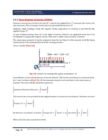
[Fig 2.26: Uniform rot rotating with angular acceleration 'α']
[Fig 2.26: Uniform rot rotating with angular acceleration 'α']
Each element on the rod experiences an inertia dmαx . This inertia contributes to a moment about
the ‘z-axis’ as show in [Fig 2.26]. All the elements along the rod contribute to the same sense of
moment. The sum of all the moments is given by:
L
2
Moment of Inertia of the rod = dmαx
0
This inertia has to be provided by the applied torque to sustain the acceleration. Therefore, we have:
L
2
Torque T = dmαx
0
L L
By Newton’s second law of motion: Torque T = dmαx = Iα , by where I = dmx
2
2
0 0
Where (I) is the mass moment of inertia.
Page 38 QP No. SSC/Q4401, Version 1.0, NSQF Level 7, Compliant with Aero and Auto Industries,