
Page 53 - C:\Users\trainee\AppData\Local\Temp\msoEAA3.tmp
P. 53
Document Title
Fundamentals of Stress and Vibration 2. Engineering Mechanics Chapter
[A Practical guide for aspiring Designers / Analysts]
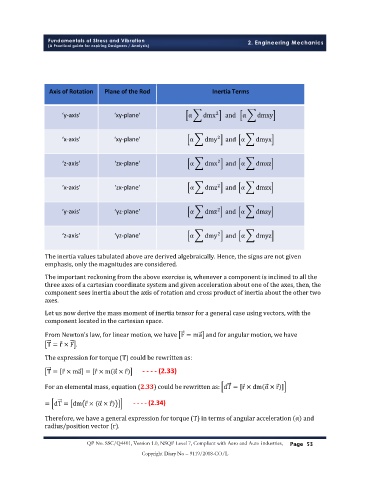
Axis of Rotation Plane of the Rod Inertia Terms
‘y-axis’ ‘xy-plane’ α dmx and α dmxy
2
‘x-axis’ ‘xy-plane’ α dmy and α dmyx
2
‘z-axis’ ‘zx-plane’ α dmx and α dmxz
2
‘x-axis’ ‘zx-plane’ α dmz and α dmzx
2
2
‘y-axis’ ‘yz-plane’ α dmz and α dmzy
‘z-axis’ ‘yz-plane’ α dmy and α dmyz
2
The inertia values tabulated above are derived algebraically. Hence, the signs are not given
emphasis, only the magnitudes are considered.
The important reckoning from the above exercise is, whenever a component is inclined to all the
three axes of a cartesian coordinate system and given acceleration about one of the axes, then, the
component sees inertia about the axis of rotation and cross product of inertia about the other two
axes.
Let us now derive the mass moment of inertia tensor for a general case using vectors, with the
component located in the cartesian space.
From Newton’s law, for linear motion, we have F = ma and for angular motion, we have
T = r × F .
The expression for torque (T) could be rewritten as:
T = r × ma = [r × m α × r - - - - (2.33)
For an elemental mass, equation (2.33) could be rewritten as: dT = r × dm α × r
= dT = dm r × α × r - - - - (2.34)
Therefore, we have a general expression for torque (T) in terms of angular acceleration α and
radius/position vector (r).
QP No. SSC/Q4401, Version 1.0, NSQF Level 7, Compliant with Aero and Auto Industries, P
Page 53 age 53
Copyright Diary No – 9119/2018-CO/L