
Page 233 - Fisika Terapan for Engineers and Scientists
P. 233
14.2 Examples of Static Equilibrium 433
✔ Checkup 14.1
QUESTION 1: Is a cyclist balanced on an upright bicycle in stable or unstable equilib-
rium? Assume the cyclist sits rigidly, and makes no effort to avoid whatever might befall
(see Fig. 14.5).
QUESTION 2: You sit in a swing, with your knees bent. If you now extend your legs fully,
how will this change the equilibrium position of the swing and your body?
QUESTION 3: (a) You hold a fishing pole with both hands and point it straight up. Is
the support force aligned with the weight? (b) You point the fishing pole horizontally.
Is the support force aligned with the weight? Is there a single support force?
QUESTION 4: Consider a cone on a table (a) lying flat on its curved side, (b) standing
on its base, (c) standing on its apex. Respectively, the equilibrium of each position is
(A) Stable, unstable, neutral (B) Stable, neutral, unstable
(C) Unstable, stable, neutral (D) Neutral, stable, unstable
(E) Neutral, unstable, stable
FIGURE 14.5 Is an upright bicycle in
unstable equilibrium?
14.2 EXAMPLES OF STATIC EQUILIBRIUM
The following are some examples of solutions of problems in statics. In these exam-
ples, the conditions of a zero sum of external forces,
F F F 0 (14.1)
1 2 3
and a zero sum of external torques,
(a)
T T T 0 (14.2)
1 2 3 90 m
are used either to find the magnitudes of the forces that hold the body in equilibrium,
or to find whether the body can achieve equilibrium at all. 30 m
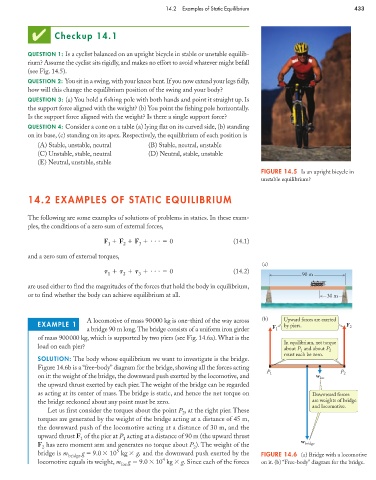
A locomotive of mass 90000 kg is one-third of the way across (b) Upward forces are exerted
EXAMPLE 1 by piers. F 2
a bridge 90 m long.The bridge consists of a uniform iron girder F 1
of mass 900000 kg, which is supported by two piers (see Fig. 14.6a). What is the
In equilibrium, net torque
load on each pier? about P and about P 2
1
must each be zero.
SOLUTION: The body whose equilibrium we want to investigate is the bridge.
Figure 14.6b is a “free-body” diagram for the bridge, showing all the forces acting
P 1 P 2
on it: the weight of the bridge, the downward push exerted by the locomotive, and w loc
the upward thrust exerted by each pier. The weight of the bridge can be regarded
as acting at its center of mass. The bridge is static, and hence the net torque on Downward forces
the bridge reckoned about any point must be zero. are weights of bridge
and locomotive.
Let us first consider the torques about the point P , at the right pier. These
2
torques are generated by the weight of the bridge acting at a distance of 45 m,
the downward push of the locomotive acting at a distance of 30 m, and the
upward thrust F of the pier at P acting at a distance of 90 m (the upward thrust
1
1
F has zero moment arm and generates no torque about P ). The weight of the w bridge
2 2
5
bridge is m bridge g 9.0 10 kg g, and the downward push exerted by the FIGURE 14.6 (a) Bridge with a locomotive
4
locomotive equals its weight, m g 9.0 10 kg g. Since each of the forces on it. (b) “Free-body” diagram for the bridge.
loc