
Page 235 - Fisika Terapan for Engineers and Scientists
P. 235
14.2 Examples of Static Equilibrium 435
weight of the locomotive would be one of the external forces acting on the com-
bined body and would have to be included in the “free-body” diagram.The vectors
in Fig. 14.6b would therefore remain unchanged.
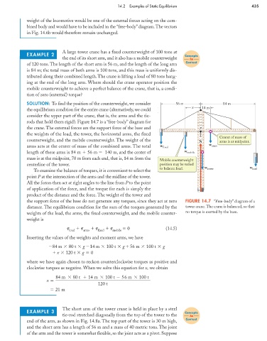
A large tower crane has a fixed counterweight of 100 tons at
EXAMPLE 2 Concepts
the end of its short arm, and it also has a mobile counterweight in
Context
of 120 tons. The length of the short arm is 56 m, and the length of the long arm
is 84 m; the total mass of both arms is 100 tons, and this mass is uniformly dis-
tributed along their combined length.The crane is lifting a load of 80 tons hang-
ing at the end of the long arm. Where should the crane operator position the
mobile counterweight to achieve a perfect balance of the crane, that is, a condi-
tion of zero (external) torque?
SOLUTION: To find the position of the counterweight, we consider 56 m 84 m
x 14 m
the equilibrium condition for the entire crane (alternatively, we could
consider the upper part of the crane, that is, the arms and the tie-
rods that hold them rigid). Figure 14.7 is a “free-body” diagram for
the crane. The external forces are the support force of the base and P P
the weights of the load, the tower, the horizontal arms, the fixed
Center of mass of
counterweight, and the mobile counterweight. The weight of the N N arms is at midpoint.
arms acts at the center of mass of the combined arms. The total w fixed w arms
length of these arms is 84 m 56 m 140 m, and the center of w mobile
mass is at the midpoint, 70 m from each end, that is, 14 m from the
Mobile counterweight
centerline of the tower. position may be varied
to balance load. w tower w load
To examine the balance of torques, it is convenient to select the
point P at the intersection of the arms and the midline of the tower.
All the forces then act at right angles to the line from P to the point
of application of the force, and the torque for each is simply the
product of the distance and the force. The weight of the tower and
the support force of the base do not generate any torques, since they act at zero FIGURE 14.7 “Free-body” diagram of a
distance. The equilibrium condition for the sum of the torques generated by the tower crane. The crane is balanced, so that
weights of the load, the arms, the fixed counterweight, and the mobile counter- no torque is exerted by the base.
weight is
0 (14.5)
load arms fixed mobile
Inserting the values of the weights and moment arms, we have
84 m 80 t g 14 m 100 t g 56 m 100 t g
x 120 t g 0
where we have again chosen to reckon counterclockwise torques as positive and
clockwise torques as negative. When we solve this equation for x, we obtain
84 m 80 t 14 m 100 t 56 m 100 t
x
120 t
21 m
The short arm of the tower crane is held in place by a steel
EXAMPLE 3 Concepts
tie-rod stretched diagonally from the top of the tower to the in
Context
end of the arm, as shown in Fig. 14.8a. The top part of the tower is 30 m high,
and the short arm has a length of 56 m and a mass of 40 metric tons. The joint
of the arm and the tower is somewhat flexible, so the joint acts as a pivot. Suppose