Page 66 - E BOOK ENGINE MECHANICAL M2
P. 66

4. SERVICE POINTS OF 4D56 ENGINE COMPONENT


                                                       5. Align the fuel injection pipe centre axis with the other
                                                       side  components  (fuel  injector  assembly  and  common
                                                       rail  assembly)  centre  axis  to  install  the  fuel  injection
                                                       pipe. Then, tighten the flare nut temporarily until the tip
                                                       of pipe (seal surface) contacts with the other side com-
                                                       ponents.

                                                             When the fuel injection pipe is installed, tighten the
                                                       Note  flare nut while shaking the pipe lightly to align the
                                                             centre axis of both components.
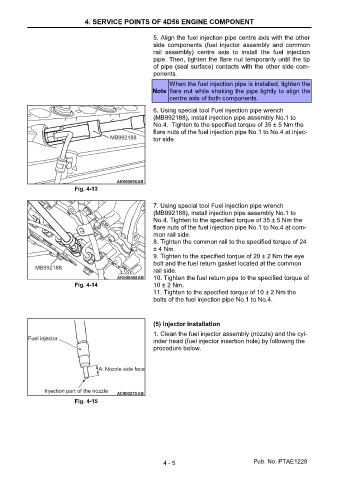
                                                       6. Using special tool Fuel injection pipe wrench
                                                       (MB992188), install injection pipe assembly No.1 to
                                                       No.4. Tighten to the specified torque of 35 ± 5 Nm the
                                                       flare nuts of the fuel injection pipe No.1 to No.4 at injec-
                                                       tor side.


                           Fig. 4-13

                                                       7. Using special tool Fuel injection pipe wrench
                                                       (MB992188), install injection pipe assembly No.1 to
                                                       No.4. Tighten to the specified torque of 35 ± 5 Nm the
                                                       flare nuts of the fuel injection pipe No.1 to No.4 at com-
                                                       mon rail side.
                                                       8. Tighten the common rail to the specified torque of 24
                                                       ± 4 Nm.
                                                       9. Tighten to the specified torque of 20 ± 2 Nm the eye
                                                       bolt and the fuel return gasket located at the common
                                                       rail side.
                                                       10. Tighten the fuel return pipe to the specified torque of
                           Fig. 4-14                   10 ± 2 Nm.
                                                       11. Tighten to the specified torque of 10 ± 2 Nm the
                                                       bolts of the fuel injection pipe No.1 to No.4.


                                                       (5) Injector Installation
                                                       1. Clean the fuel injector assembly (nozzle) and the cyl-
                                                       inder head (fuel injector insertion hole) by following the
                                                       procedure below.


                           Fig. 4-15


                                                          4 - 5                           Pub. No. PTAE1228
   61   62   63   64   65   66   67   68   69   70   71