
Page 192 - Basic Course
P. 192
KNX BASIC COURSE
6 Interlinked building structures
The Building View is indispensable for the project designer of a larger project, for
documentation purposes alone. Only in the Building View, can it be completely
understood where each component is installed. You have to maintain the following
structure in ETS: buildings – building part (floor) – rooms/cabinet. However, there is an
exception to the rule: room/cabinet can also be located directly under a building. Devices
can be inserted in four locations, in a room / distribution cabinet, in the “Devices” view, in
the “Project Root” view or in the “Topology” view. All the devices that are not created via
the building structure (in the topology and trades) are inserted first. They should be linked
in the correct place in the Building View at the latest when the project is completed.
A problem regularly occurs if a building has not been built according to the “standard” e.g.
in other words it does not have clearly recognisable floors. In this case, the interlinking of
the building parts will help you further. This structural element can be freely subdivided;
moreover rooms/cabinets can also be inserted directly in buildings. This may be
necessary when you need to design a project for a sports centre for instance. The rooms
are inserted in the building and there are no floors.
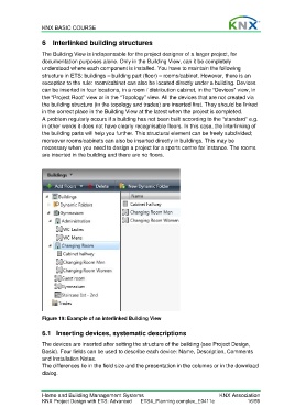
Figure 19: Example of an interlinked Building View
6.1 Inserting devices, systematic descriptions
The devices are inserted after setting the structure of the building (see Project Design,
Basic). Four fields can be used to describe each device: Name, Description, Comments
and Installation Notes.
The differences lie in the field size and the presentation in the columns or in the download
dialog.
Home and Building Management Systems KNX Association
KNX Project Design with ETS: Advanced ETS4_Planning complex_E0411c 16/59