Page 1296 - YG 2019
P. 1296

TECHNICAL                                                                                                             TECHNICAL
                              DATA                     SUPER CUTTING END MILLS                                                                      DATA                      SUPER CUTTING END MILLS


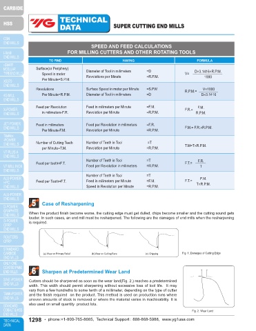
                                            SPEED AND FEED CALCULATIONS                                                                7    Resharpening Peripheral Cutting Edge
                                 FOR MILLING CUTTERS AND OTHER ROTATING TOOLS

                        TO FIND                            HAVING                              FORMULA                                      1  RESHARPENING PERIPHERAL CUTTING EDGE

                  Surface(or Periphery)   Diameter of Tool in milimeters    =D
                     Speed in meter       Revolutions per Minute       =R.P.M.           V=   D×3.1416×R.P.M.                                 The geometry of relief angle in an end mill consists of three methods as shown in Fig.3 concave, flat, and
                                                                                                                                              eccentric. Recently, most end mills have the eccentric relief(eccentric sharpening).  In this method, since the relief
                     Per Minute=S.P.M.                                                            1000                                        is formed an eccentric are surface in cylindrical grinding method, the roughness of the finished surface of the relief
                                                                                                                                              improves and the strength of cutting edge increase at the same time.(Fig.4) As a result, the tool life is improved.
                  Revolutions             Surface Speed in meter per Minute   =S.P.M     R.P.M.=  V×1000
                     Per Minute=R.P.M.    Diameter of Tool in milimeters   =D                    D×3.1416                                                Eccentric                    Concave                       Flat


                  Feed per Revolution     Feed in milimeters per Minute   =F.M.          F.R.=  F.M.
                     in milimeters-F.R.   Revolution per Minute        =R.P.M.                R.P.M.

                  Feed in milimeters      Feed per Revolution in milimeters   =F.R.
                     Per Minute-F.M.      Revolution per Minute        =R.P.M.           F.M.= F.R.×R.P.M.
                                                                                                                                                                               Fig. 3. Three Types of Primary Relief
                  Number of Cutting Teeth  Number of Teeth in Tool      =T
                     per Minute=T.M.      Revolution per Minute        =R.P.M.           T.M=T×R.P.M.                                                              Wheel Head Swing                           α=Relief Angle
                                                                                                                                                                                                              Ø=Helix Angle
                                                                                                                                                                                                              Θ=Form of Swing Angle
                                          Number of Teeth in Tool      =T                      F.R.                                                                      Wheel Formed        A                Formula:tan(Θ)°=tan(α)°×tan(Ø)°
                  Feed per tooth=F.T.                                                    F.T.=
                                          Feed per Revolution in milimeters   =R.P.M.           T
                                                                                                                                                                  Section A-A
                                                                                                                                                                                                      Θ
                                          Number of Teeth in Tool      =T                                                                                                    α
                                                                                                F.M.
                  Feed per Tooth=F.T.     Feed in milimeters per Minute   =F.M.          F.T.=  T×R.P.M.                                                                                          Ø
                                          Speed in Revolution per Minute   =R.P.M.                                                                                                           A

                5    Case of Resharpening

                                                                                                                                                                              Fig. 4. Toothing of Eccentric Relief Angle
               When the product finish become worse, the cutting edge must get dulled, chips become smaller and the cutting sound gets
               louder. In such cases, an end mill must be resharpened. The following are the damages of end mills when the resharpening     2
               is required.                                                                                                                   ANGLE OF WHEEL INCLINATION
                                                                                                                                              Eccentric relief is produced with a plain wheel positioned with its axis parallel or at a slight angle with the cutter
                                                                                                                                              axis. The degree of relief is varied by changing the angle of wheel inclination.
                                                                                                                                                                Table 1. RECOMMENDED RELIEF ON END MILLS

                                                                                                                                                  Mill       Eccentric relief   Checking     Wheel Angles(Deg.)Θ      Radial   Clearance
                      (a) Wear on Primary Relief  (b) Wear on Cutting Face  (c) Chipping  Fig. 1. Damages of Cutting Edge                       Diameter    indicator drop for   Distance  15°     30°       60°      Relief   Angles(α2)
                                                                                                                                                (inches)   relief Angles shown           Helix     Helix     Helix   Angles(α1)
                                                                                                                                                   -        Min      Max.        -       *Angle   *Angle    *Angle    *Angle    *Angle
                6    Sharpen at Predetermined Wear Land                                                                                          1/8      .0040     .0052      .015     4°42′     10°02′   27°58′    17°03′      25°
                                                                                                                                                                               .020
                                                                                                                                                                    .0050
                                                                                                                                                          .0035
                                                                                                                                                 1/4
                                                                                                                                                                                        3°15′
                                                                                                                                                                                                           20°12′
                                                                                                                                                                                                                                 25°
                                                                                                                                                                                                  6°59′
                                                                                                                                                                                                                     12°00′
                                                                                                                                                 1/2      .0040     .0053      .025     2°51′     6°07′    17°51′    10°32′      25°
               Cutters should be sharpened as soon as the wear land(Fig. 2.) reaches a predetermined
               width. This width should permit sharpening without excessive loss of tool life.  It may                                            1       .0038     .0055     1/32      2°16′     4°54′    14°27′     8°27′      25°
               vary from a few hundreths to some tenth of a millimeter, depending on the type of cutter                                         1-1/2     .0033     .0050     1/32      2°02′     4°22′    12°57′     7°33′      25°
               and the finish required  on the product. This method is used on production runs where                                              2       .0033     .0050     1/32      2°02′     4°22′    12°57′     7°33′      25°
               uneven amounts of stock is removed or where the material varies in machinability. It is                                        The actual at the radial relief angle is normally kept within the range shown but may be varied to suit the cutter
               also used on small quantity  product lots.                                                                                     material, the work material and the operating conditions.
                                                                                                                                              * Angle is calculated from the basic mean at the radical angle.
                                                                                            Fig. 2. Wear Land
               1298   • phone:+1-800-765-8665,  Technical Support : 888-868-5988,  www.yg1usa.com                                                       phone:+1-800-765-8665,  Technical Support : 888-868-5988,  www.yg1usa.com  •  1299
   1291   1292   1293   1294   1295   1296   1297   1298   1299   1300   1301