
Page 1299 - YG 2019
P. 1299
TECHNICAL TECHNICAL
DATA SUPER CUTTING END MILLS DATA SUPER CUTTING END MILLS
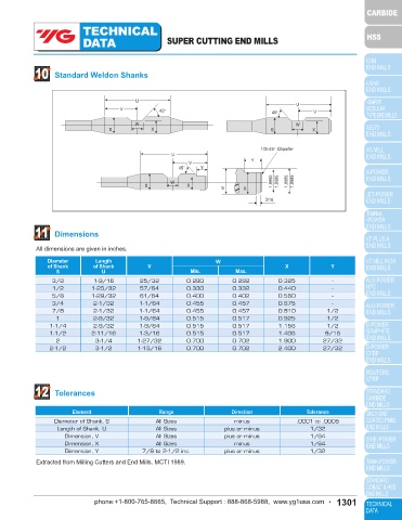
8 Resharpening End Teeth A. Use Plain B. Use Plain 10 Standard Weldon Shanks
Wheel
Wheel
End Mill
The three necessary operations and one Notch Angle may be
option feature, along with setup suggestions traversed
are shown in Fig.5 A to D in each drawing, the into wheel U U
in this direction
shaded area indicates the surface being V 45° 45° V
ground. End Mill may
be traversed Or passed under W W
into wheel in the wheel Or passed under S X S X
this direction the wheel
1st Operation Notch slightly beyond center 2nd Operation - Secondary clear end 1/3×45° Chamfer
U
V Y
C. 5° ~12° primary D. Use Plain 45° Y
1/2~5 End end relief Wheel
concavity Traverse W 1.9990 1.9995 1.9995 1.9999
end mill S X
Use Cup under the S X
Wheel
wheel
3/16
Or end mill
End Mill may be
may be traversed
traversed into wheel
under end Or wheel may be traversed in this direction
face wheel across end of end mill 11 Dimensions
(optional)
3rd Operation-Primay relieve end 4th Operation-Clear and at junction All dimensions are given in inches.
of Secondary clear & notch
Fig 5. PROCEDURE FOR SHARPENING END OF 2 FLUTE SQUARE END MILLS Diameter Length W
of Shank of Shank V Min. Max. X Y
U
S
9 9 Inspection 3/8 1-9/16 25/32 0.280 0.282 0.325 -
1/2 1-25/32 57/64 0.330 0.332 0.440 -
The inspection is calculated by using the formula shown in Table1. 5/8 1-29/32 61/64 0.400 0.402 0.560 -
Procedure To Check 3/4 2-1/32 1-1/64 0.455 0.457 0.675 -
Radial Relief Angles 7/8 2-1/32 1-1/64 0.455 0.457 0.810 1/2
With Indicators. 1 2-9/32 1-9/64 0.515 0.517 0.925 1/2
1-1/4 2-9/32 1-9/64 0.515 0.517 1.156 1/2
1. Mount the cutter to rotate freely with no end movement. 1-1/2 2-11/16 1-3/16 0.515 0.517 1.406 9/16
2. Adjust the sharp pointed indicator to bear at the very tip of the cutting edge, pointing in a radial line, 2 3-1/4 1-27/32 0.700 0.702 1.900 27/32
shown in Figure6 2-1/2 3-1/2 1-15/16 0.700 0.702 2.400 27/32
3. Roll the cutter the tabuleted amount gives under “checking distance” using the second indicator as
control.
4. Consult chart for amount of drop for the particular diameter and relief angle.
Radial Relief Peripheral Cutting Edge Cutting Angle
12 Tolerances
Primary
Land Width Element Range Direction Tolerance
Diameter of Shank, S All Sizes minus .0001 to .0005
α1
Indicator Drop α2 Length of Shank, U All Sizes plus or minus 1/32
Dimension, V All Sizes plus or minus 1/64
Dimension, X All Sizes minus 1/64
Distance
Dimension, Y 7/8 to 2-1/2 inc. plus or minus 1/32
Checking
Checking
Distance Indicator Drop Extracted from Milling Cutters and End Mills. MCTI 1989.
Fig. 6. Indicator Set-Up for Checking
1300 • phone:+1-800-765-8665, Technical Support : 888-868-5988, www.yg1usa.com phone:+1-800-765-8665, Technical Support : 888-868-5988, www.yg1usa.com • 1301