
Page 1301 - YG 2019
P. 1301
TECHNICAL TECHNICAL
DATA SUPER CUTTING END MILLS DATA SUPER CUTTING END MILLS
13 Combination Shanks for End Mills 16 Troubleshooting in Endmilling
Right hand End Mill shank shown. For Trouble Occurrences of trouble Countermeasures
left hand End Mills flat “F” and pin
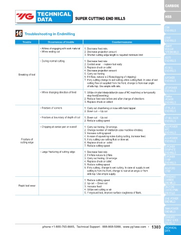
groove “K” should be located 180° from •At time of engaging with work material 1. Decrease feed rate.
that shown, maintaining 12° relationship G •When ending cut 2. Decrease projection amount
of flat “F” and groove “K” 3. Shorten cutting edge length to required minimum limit
K F 45° •During normal cutting 1. Decrease feed rate
E 2. Control wear → replace tool early
L 3. Replace chuck or collet
B 4. Decrease projection amount
Breaking of tool 5. Carry out honing
90° 1/2K H C 45° 6. If 4 flute, reduce to 2 flute(clogging of chipping)
7. If dry cutting change to wet cutting utilize cutting fluid. In case of wet
cutting flow oil supplied from the front, change to from rear angle
A J D of side top. Use ample with rate.
•When changing direction of feed 1. Utilize circular interpolation(in case of NC machine) or temporarily
.015 stop feed(Dowelling)
M CENTRAL WITH “K”
12° 2. Reduce feed rate before and after change of directions
3. Replace chuck or collect
14 Dimensions
•Fracture of corners 1. Carry out chamfering or nose with hand lapper.
All dimensions are given in inches. 2. Down cut → Up cut
Diameter Length •Fracture at boundary of depth of cut 1. Down cut → Up cut
of Shank of Shank B C D E F G H J K M 2. Reduce cutting speed
A L
1-1/2 2-11/16 1-3/16 0.515 1.406 1-1/2 0.515 1.371 9/16 1.302 0.377 7/16 •Chipping at center part or overall 1. Carry out honing. Or enlarge.
2 3-1/4 1-23/32 0.700 1.900 1-3/4 0.700 1.809 5/8 1.772 0.440 1/2 2. Change number of rotation(in case machine vibrates)
2-1/2 3-1/2 1-15/16 0.700 2.400 2 0.700 2.312 3/4 2.245 0.503 9/16 3. Increase cutting speed
4. In ease of squeaking noise during cutting, increase feed.
Fracture of 5. It dry cutting use cutting fluid or blow air.
cutting edge 6. Replace chuck or collet
7. Reduce cutting speed
15 Tolerances
•Large fracturing of cutting edge 1. Decrease feed rate
2. If 4 flute reduce to 2 flute
Element Direction Tolerance
3. Carry out honing. Or enlarge
Diameter of Shank, A minus .0001 to .0005 4. Replace chuck or collet
Length of Shank, L plus or minus 1/32 5. Reduce cutting speed
Dimension, B plus or minus 1/64 6. If dry cutting, change to wet cutting. In case oil supply in wet
Dimension, C plus .002 cutting is from the front, change to rear at an angle or from
Dimension, D minus 1/64 side top. Use ample supply.
Dimension, E plus or minus 1/64
Dimension, F plus or minus .005 1. Reduce cutting speed
Dimension, G minus 1/64 Rapid tool wear 2. Up cut → Down cut
3. Increase feed
Dimension, H plus 1/64 4. Utilize wet cutting or air
Dimension, J plus or minus .002 5. If reground tool, improve surface roughness of flank.
Dimension, K plus .003
Extracted from Milling Cutters and End Mills. MCTI 1989.
1302 • phone:+1-800-765-8665, Technical Support : 888-868-5988, www.yg1usa.com phone:+1-800-765-8665, Technical Support : 888-868-5988, www.yg1usa.com • 1303