
Page 694 - CarrLaneCatalog_2019ed-c.pdf
P. 694
Electric Power Units 7250/5000 psi max
Single and double acting
CONTROL OPTIONS: Electric Power Units SAFETY FEATURES: Fail-safe operation in case Units can also be mounted on the machine
are offered with three standard hydraulic/ of electrical-power failure since the solenoid- tool using an angle bracket. The photo below
electrical-control options: (1) Single acting, operated clamping valves are de-energized in shows an overhead traverse bar for convenient
(2) Double acting, (3) Single acting for two “clamped” position. These valves are poppet hose arrangement. Push-button switches are
independent fixtures. type, so they provide tight zero leakage sealing. installed within the operator’s reach.
Units are also equipped with fluid-level and fluid-
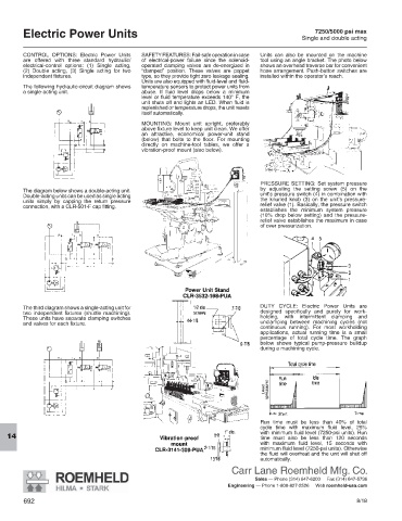
The following hydraulic-circuit diagram shows temperature sensors to protect power units from
a single-acting unit. abuse. If fluid level drops below a minimum
level or fluid temperature exceeds 140° F, the
unit shuts off and lights an LED. When fluid is
replenished or temperature drops, the unit resets
itself automatically.
MOUNTING: Mount unit upright, preferably
above fixture level to keep unit clean. We offer
an attractive, economical power-unit stand
(below) that bolts to the floor. For mounting
directly on machine-tool tables, we offer a
vibration-proof mount (also below).
PRESSURE SETTING: Set system pressure
The diagram below shows a double-acting unit. by adjusting the setting screw (5) on the
Double-acting units can be used as single acting unit’s pressure switch (4) in combination with
units simply by capping the return pressure the knurled knob (3) on the unit’s pressure-
connection, with a CLR-501-F cap fitting. relief valve (1). Basically, the pressure switch
establishes the minimum system pressure
(10% drop below setting) and the pressure-
relief valve establishes the maximum in case
of over pressurization.
The third diagram shows a single-acting unit for DUTY CYCLE: Electric Power Units are
two independent fixtures (shuttle ma chin ing). designed specifically and purely for work-
These units have separate clamping switches holding, with intermittent clamping and
and valves for each fixture. un clamping between machining cycles (not
continuous running). For most workholding
ap plications, actual running time is a small
percentage of total cycle time. The graph
below shows typical pump-pressure buildup
during a machining cycle.
Run time must be less than 40% of total
cycle time with maximum fluid level, 25%
with minimum fluid level (7250-psi units). Run
time must also be less than 120 seconds
14
with maximum fluid level, 15 seconds with
minimum fluid level (7250-psi units). Otherwise
the fluid will overheat and the unit will shut off
automatically.
Carr Lane Roemheld Mfg. Co.
Sales — Phone (314) 647-6200 Fax (314) 647-5736
Engineering — Phone 1-800-827-2526 Web roemheld-usa.com
692 8/18