Page 16 - Robot Design Handbook ROBOCON Malaysia 2019
P. 16

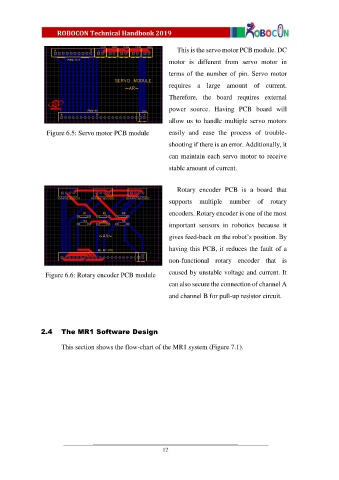
This is the servo motor PCB module. DC

                                                            motor  is  different  from  servo  motor  in
                                                            terms  of  the  number  of pin.  Servo  motor

                                                            requires  a  large  amount  of  current.
                                                            Therefore,  the  board  requires  external

                                                            power  source.  Having  PCB  board  will

                                                            allow us  to  handle multiple servo motors
                 Figure 6.5: Servo motor PCB module         easily  and  ease  the  process  of  trouble-

                                                            shooting if there is an error. Additionally, it
                                                            can maintain each servo motor to receive

                                                            stable amount of current.


                                                               Rotary  encoder  PCB  is  a  board  that
                                                            supports  multiple  number  of  rotary

                                                            encoders. Rotary encoder is one of the most
                                                            important  sensors  in  robotics  because  it

                                                            gives feed-back on the robot’s position. By

                                                            having this PCB, it reduces the fault of a
                                                            non-functional  rotary  encoder  that  is


                 Figure 6.6: Rotary encoder PCB module      caused by unstable voltage and current. It
                                                            can also secure the connection of channel A
                                                            and channel B for pull-up resistor circuit.


               2.4     The MR1 Software Design

                       This section shows the flow-chart of the MR1 system (Figure 7.1).


                                                          12
   11   12   13   14   15   16   17   18   19   20   21