Page 15 - Robot Design Handbook ROBOCON Malaysia 2019
P. 15

stop button in order to cut off the power of

                                                               the  motor  so  that  the  robot  can  stop
                                                               immediately  if  there  is  an  error  in  the

                                                               system  during  testing  process.  In  the
                                                               middle, there is a LCD display that acts as

                                                               a  GUI  (Graphic  User  Interface)  and

                                                               displaying  every  information  that  the
                                                               programmer wants to display for feed-back

                                                               output.


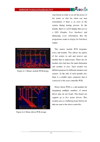
                                                                  This  master  module  PCB  integrates
                                                               every sub-module. This allows the agility

                                                               of  the  system  to  add  and  remove  any
                                                               module that is unneccesary. There are six

                                                               module slots that have the same dimension
                                                               and  number  of  pins.  Each  module  has

                     Figure 6.3: Master module PCB design      different purpose for different actuators and
                                                               sensors.  At  the  side  of  each  module  slot,

                                                               there  is  a  double  layer  connector  that  is

                                                               connected to the main controller PCB.


                                                                  Motor driver PCB is a sub-module for
                                                               integrating  multiple  numbers  of  motor

                                                               driver pins  on one board. This  board can
                                                               support  up  to  five  motor  drivers.  This

                                                               module acts as a buffering board before the
                                                               data are sent to the micro-controller.


                    Figure 6.4: Motor driver PCB design


                                                             11
   10   11   12   13   14   15   16   17   18   19   20