
Page 14 - Robot Design Handbook ROBOCON Malaysia 2019
P. 14
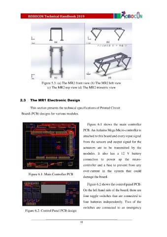
Figure 5.3: (a) The MR2 front view (b) The MR2 left view
                                   (c) The MR2 top view (d) The MR2 trimetric view


               2.3     The MR1 Electronic Design

                       This section presents the technical specifications of Printed Circuit

                Board (PCB) designs for various modules.

                                                               Figure  6.1  shows  the  main  controller

                                                            PCB. An Arduino Mega Micro-controller is

                                                            attached to this board and every input signal
                                                            from the sensors and output signal for the

                                                            actuators  are  to  be  transmitted  by  the
                                                            modules.  It  also  has  a  12  V  battery

                                                            connection  to  power  up  the  micro-
                                                            controller and a fuse to prevent from any

                                                            over-current  in  the  system  that  could
                     Figure 6.1: Main Controller PCB
                                                            damage the board.

                                                               Figure 6.2 shows the control panel PCB.

                                                            On the left hand side of the board, there are
                                                            four toggle switches that are connected to

                                                            four  batteries  independently.  Two  of  the

                                                            switches  are  connected  to  an  emergency
                   Figure 6.2: Control Panel PCB design


                                                          10