
Page 181 - Robot Design Handbook ROBOCON Malaysia 2019
P. 181
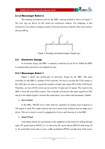
2.1.2 Messenger Robot 2
The rotating mechanism used for the MR2 walking method is shown in Figure 3.
The four legs are driven by DC motor for continuous rotation. The challenge in this
mechanism is to achieve rotating symmetry between each leg so that the robot stays balance
during walking.
Figure 3: Rotating mechanism legged (Single leg)
2.2 Electronic Design
In electronic design, the MR1 is manually controlled by the driver. While the MR2
is autonomously operated to accomplish the task.
2.2.1 Messenger Robot 1
Figure 4 shows the architecture of electronic design for the MR1. The main
controller for the MR1 is Arduino UNO controller. We have cascaded the UNO master to
the UNO slave in order to expand that number of input and output (I/O) of the UNO board.
Therefore, we have 40 I/O which can be used for 14 input and 21 output. The input for the
MR1 is from the wired PS2 joystick. The controller will process the input signal from PS2
and give the output signal to activate the omniwheel, servo motor and pneumatic cylinder.
Servo Motor
In the MR1, MG955 servo motor with the capability of rotating from 0 degrees to
180 degree is used. We control directly the servo motor from Arduino and not using servo
driver. This servo motor is used for gripping the Gerege and releasing it to the MR2.
Omni Wheel
Four Omni wheels are used based on the capability of the motor for sliding left and
right. DC geared motor 4G45Z 12 V is driven by DC motor driver MDC30 with rating 30
A. To control this motor driver, pulse width modulation (PWM) and direction of the motor
177