
Page 254 - Robot Design Handbook ROBOCON Malaysia 2019
P. 254
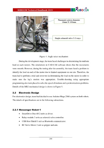
Figure 4: Angle raiser mechanism
During the development stage, the team faced challenges in determining the uniform
load on each motors. The simulations in CAD-CAE software shows that the movements
were smooth. However, during the testing after the assembly, the team faced a problem to
identify the load on each of the motor due to limited equipment on our site. Therefore, the
team had to perform a trial-and-error test in determining the load on the motor in order to
make sure the leg’s motion was appropriate. Trouble-shooting using appropriate
programming also took placed to solve the speed of motions and synchronizations problems.
Details of the MR2 mechanical design is shown in Figure 5.
2.2 Electronic Design
For electronics design, team had decided to use Arduino Mega 2560 system on both robots.
The details of specifications are in the following subsections.
2.2.1 Messenger Robot 1
SmartDrive Duo-60 2 units as driver.
Relay module 3 units as solenoid valve controller.
USB Host Shield 1 unit as Bluetooth communicator.
RC Servo Motor 2 unit as gripper and arm.
250