
Page 105 - APPLIED PROCESS DESIGN FOR CHEMICAL AND PETROCHEMICAL PLANTS, Volume 1, 3rd Edition
P. 105
Fluid Flow 89
summation, these equivalent lengths for all the compo- Table 2-5
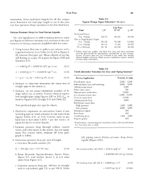
nents determine the total pipe length to use in the pres- Typical Design Vapor Velocities* (ft/sec)
sure loss (pressure drop) equations to be described later.
Line Sizes
Fluid ::;6" 8"-12" � 14"
Friction Pressure Drop for Non-Viscous Liquids
Saturated Vapor
The only significance in differentiating between water Oto 50 psig 30-115 50-125 60-145
and liquids of different densities and viscosities is the con- Gas or Superheated Vapor
venience in having a separate simplified table for water. Oto 10 psig 50-140 90-190 110-250
11 to 100 psig 40-115 75-165 95-225
101 to 900 psig 30- 85 60-150 85-165
1. Using known flow rate in gallons per minute and a
suggested velocity from Tables 2-4 to 2-8 or Figure 2- * Values listed are guides, and final line sizes and flow velocities
must be determined by appropriate calculations to suit circum-
22, estimate first pipe size. Mean velocity of any liq- stances. Vacuum lines are not included in the table, but usually
uid flowing in a pipe [3] is given by Figure 2-22 and tolerate higher velocities. High vacuum conditions require careful
Equation 2-51. pressure drop evaluation.
2
v = 0.408 Qld = 0.0509 \V/(d 2) (p), ft/sec (2-51)
Table 2-6
1
d = (0.408 Q/v) 1 2 = (0.0509 W/vp) 1 2, in. (2-53) Usual Allowable Velocities for Duct and Piping Systems*
1
v = q/A = w,/Ap = 183.3 (q/d 2), ft/sec (2-54) Service/ Application Velocity, ft./min.
Forced draft ducts 2,500 - 3,500
2. Estimate or otherwise determine the linear feet of Induced-draft flues and breeching 2,000 - 3,000
straight pipe in the system, L. Chimneys and stacks 2,000
Water lines (max.) 600
3. Estimate (or use actual tabulation) number of fit- 10,000
tings, valves, etc. in system. Convert these to equiva- High pressure steam lines 12,000 - 15,000
Low pressure steam lines
lent straight pipe using Figures 2-20 or 2-21, Leg, or Vacuum steam lines 25,000
head by Figures 2-12 through 2-16 and Table 2-2. Compressed air lines 2,000
Refrigerant vapor lines
Note preferred pipe size type for charts. High pressure 1,000 - 3,000
Low pressure 2,000 - 5,000
4. Determine expansion or contraction losses, if any, Refrigerant liquid 200
including tank or vessel entrance or exit losses from Brine lines 400
Figures 2-l2A, 2-15, or 2-16. Convert units to psi, Ventilating duns 1,200 - 3,000
head loss in feet times 0.4331 = psi (for water), or Register grilles 500
adjust for Sp Gr of other liquids. �By permission, Chemical Engineer's Handbook, 3rd Ed., l\kGraw-Hill Book
Co., New York, N.Y., p. 1642.
5. Estimate pressure drop through orifices, control
valves, and other items in the system, but not equip-
ment. For control valves, estimate 11P from para-
graph to follow.
lish p1pmg system friction pressure drop (loss),
6. Determine pressure drop per unit of length. liquids (Figure 2-23):
a. Calculate Reynolds number [3]
R, = 50.6 Qp/(dµ) = 6.31 \V/(dµ) (2-16) For turbulent flow: �P/l 00 ft = 0.0216 f pQ / d 5 (2-55)
2
b. From Reynolds Number-Friction Factor Chart, = 0.000336 rw 2; ( d 5) (p) (2-55A)
Figure 2-3, read friction factor, f, at £/ d value
taken from Figure 2-11.
For laminar flow: �P/100 ft= 0.0668 (µ) v/d 2 (2-56)
c. Calculate presst,re drop per 100 feet of (straight
and/or equivalent) pipe [3] as psi/100 ft. Estab- = 0.0273 (µ) Q/d 4 (2-56A)