
Page 109 - APPLIED PROCESS DESIGN FOR CHEMICAL AND PETROCHEMICAL PLANTS, Volume 1, 3rd Edition
P. 109
Fluid Flow 93
Correction Factors Factors tO consider in evaluating the control valve pres-
Volur of C 60 70 80 90 100 110 120 130 140 sure drop are:
Multi lier to Correct Chart 2.57 1.93 1.50 1.22 1.0 .84 .71 .62 .54
A Allowance for increase in friction drop
Establish the ratio of the maximum antir:ipated flow rate
for system, QM, to the design basis rate, Q or QM/Q .
0
0
When Q:vr is not known, nor can it be anticipated, use:
Q.,1/Q0 of 1.1 for flow control and 1.25 for level pressure
and temperature control valves to anticipate the flow rate
transients as the control loop recovers from a distur-
bance [9J.
At the maximum flow rate QM, the friction drop will
become:
I (2-62)
IL
The increase in pressure drop will be:
(2-63)
1-- .... � <!l.,,. � '4-"°+-l-++l. � /:.-l c;,i.t.\ \ .� \
3 I/ [...,' \ �\� ' � . y (2-64)
2v � vv"" � K J,.t,. \�
1.q,L _ l___.::t: . 2.....L . 3.l:4..J . 5...:1.. . 7u.l.1.. . 0 � ..1.2£..L.3...14_J5...J....::7LLI- 1 0-2.i..o-30::':-'-'50 � 70'."" I OO F0 may not necessarily be very accurate at the design stage
where final drawing dimensions for the system are being
Pressure Loss in Feet of Water per 100 Feet
estimated. For this reason a 10% increase allowance is
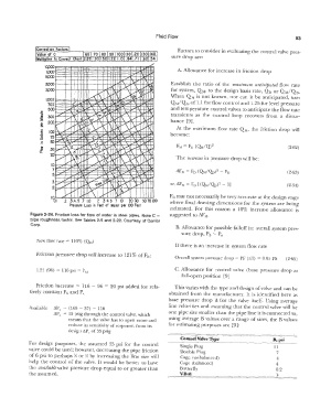
Figure 2-24. Friction loss for flow of water in steel pipes. Note C = suggested to £\FM.
pipe roughness factor. See Tables 2-9 and 2-22. Courtesy of Carrier
Corp.
B. Allowance for possible falloff in: overall system pres-
sure drop, P5 - Pe
New flow rate = 110% (Q 0)
If there is an increase in system flow rate
F
Friction pressure drop will increase to 121 % of 0;
Overall system pressure drop = PF (all) = 0.05 PS (2-65)
1.21 (96) = 116 psi = FM C. Allowance for control valve (base pressure drop at
full-open position [9J
Friction increase =c 116 - 96 = 0 20 psi added for rela- This varies with the type and design of valve and can be
tively constant Ps and P.,
obtained from the manufacturer. It is identified here as
base pressure drop B for the valve itself. Using average
Available �pc= (168 - 37) - 116 line velocities and assuming that the control valve will be
�Pc = 15 psig through the control valve, which one pipe size smaller than the pipe line it is connected to,
means that the valve has to open more and using average B values over a range of sizes, the B values
reduce its sensitivity of response, from its for estimating purposes are [9]:
design �pc of 35 psig
Control Valve Type B,p_s_ i __
For design purposes, the assumed 35 psi for the control
valve could be used; however, decreasing the pipe friction Single Plug 11
Double Plug
7
of 6 psi to perhaps X or Y. by increasing the line size will Cage (unbalanced) 4
help the control of the valve. It would be better to have Cage (balanced) 4
the available valve pressure drop equal to or greater than Butterfly 0.2
the assumed. V-Ball l