
Page 155 - APPLIED PROCESS DESIGN FOR CHEMICAL AND PETROCHEMICAL PLANTS, Volume 1, 3rd Edition
P. 155
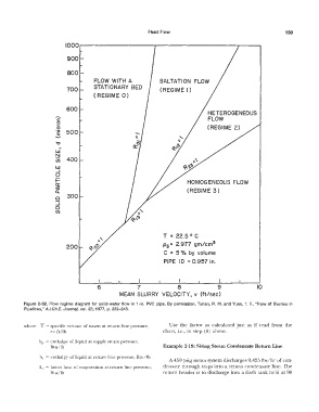
Fluid Flow                                           139

                          1000


                           900

                           800
                                     FLOW  WITH  A             SALTATION  FLOW
                           700       STATIONARY  BED           (REGIME  I)
                                     ( REGIME  O)


                       -   600                                                   HETEROGENEOUS
                                                                                 FLOW
                       c
                       0
                       �
                      -    500                                                   (REGIME  2)
                       -�
                       E
                       ,:,
                        �
                       w
                       �
                       Cl)   400
                       w
                       ..J
                       o
                       i=
                       a::                                               HOMOGENEOUS  FLOW
                       �                                                 (REGIME  3)
                       a   300
                       ..J
                      0
                      Cl)


                                                                T  =  22.5 ° C

                           200                                  Ps =  2.977  gm/cm 3
                                                                C  =  5 %  by  volume
                                                                PIPE  ID  =  0.957 in.


                                       6              7               8              9               10
                                               MEAN  SLURRY  VELOCITY,  v  (ft/sec)

          Figure  2-52.  Flow  regime diagram  for solid-water flow  in  1-in.  PVC  pipe.  By  permission,  Turian,  R.  M.  and  Yuan,  T.  F.,  "Flow  of Slurries  in
          Pipelines," A.I.Ch.E.  Journal,  vol. 23, 1977,  p. 232-243.


          where  V  =  specific volume of steam at return  line pressure,   Use  the  factor  so  calculated just  as  if read  from  the
                     Ci:  ft/lb                                 chart,  i.e., in step  (8)  above.

                hp  =  enthalpy of liquid at supply  steam pressure,
                     Btu/lb                                     Example 2-19: Sizing Steam Condensate Return Line

                hr  =  enthalpy of liquid at return line pressure,  Btu/lb
                                                                  A 450 psig steam system discharges 9,425 lbs/hr of con-
                L,  =  latent heat of evaporation at return  line pressure,   densate  through traps into a return condensate line. The
                     Btu/lb                                     return  header is  to  discharge  into  a flash tank held at 90