
Page 153 - APPLIED PROCESS DESIGN FOR CHEMICAL AND PETROCHEMICAL PLANTS, Volume 1, 3rd Edition
P. 153
Fluid Flow 137
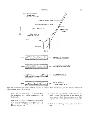
Note: V = mean velocity
L = pipe length
�P = total pressure drop
HOMOGENEOUS FLOW----N
HETEROGENEOUS FLOW
�
c.. SALTATION FLOW
<] CLEAR WATER
...!,. FLOW
O')
� FLOW WITH A
STATIONARY BED
log vc
log v
HOMOGENEOUS FLOW
HETEROGENEOUS FLOW
-+ SALTATION FLOW
FLOW WITH A
STA TIO NARY BED
Figure 2-50. Representative plot of pressure drop for slurry flow. By permission, Turian, R. M. and Yuan, T. F., "Flow of Slurries in Pipelines,"
AI.Ch.E. Journal, vol. 23, 1977, p. 232-243.
8. Divide the load factor (step 1) by the value from 10. For pipe sizes larger than 3-in., follow the steps (1)
the "factor scale" of (7) above, obtain ft/min/ (100 thru (8) above. Then enter the vertical scale at the
lb/hr load). steam pressure of (1) above, and more to the 3-in.
pipe size and down to the horizontal velocity scale.
9. Enter chart on horizontal velocity line, go vertical-
ly up to the steam pressure of (l) above, and read
pipe size to the next largest size if the value falls 11. Divide the result of step 8 above by the result of step
between two pipe sizes. (10).