Page 200 - APPLIED PROCESS DESIGN FOR CHEMICAL AND PETROCHEMICAL PLANTS, Volume 1, 3rd Edition
P. 200

Pumping of Liquids                                       171


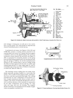
                                                 Turn  Pump  Over by  Hand  before  Starling   No.   Parr  Nome
                                                 Molar  lo  Ht Iha!  II  Turn1  Freely.
                                                                                        I.   Pump  Co&ing
                                                                                       3.   Impeller
                                                              Lubricate  Stuffing  Box   4.   Pump  Frome
                                                              By  Circulating  Water  or   7.   Split  Gland
                                                              Clear Solution  lhru     10.   Shoff
                                                              Connections •x• a •y•.   12.  Lantern  Ring
                                                                                       13.   Pocking
                                                                                      44.   Nipple  (2)
                  Tong  of  Key                                                        55.   Thrower  Ring
               Must  be  Located                                                       56.   Rubber  Ring
                        Here                                                           59.   Re&ilient  Sleeve
                                                                                      60.   S hafl Sleeve
                                                                                       61.  Rubber  Ring
                                                                                       62.   Retaining  Ring
                                                                                       74.   Rubber  Ring
                                                                                      79.   Cop&crew  (6)
                                                                                      82.   Gland  Yoke
                                                                                      88.   Key
                                                                                      98.   Shafi Sleeve  Ext'n.
                                                                                      106.   Tie  Rod
                                                                                      144.   Key
                                                                                      164.   Wosher (2)
                                                                                      165.   Retainer (2)
                                                                                      167.   Rubber  Ring  (2)

                   Figure 3-16.  Stuffing  box details lined pump with  porcelain or teflon® shaft sleeve. (Courtesy Dorr-Oliver,  Inc.)

       nent  damage  or  destruction  on  only  one  or  two  revolu-
       tions  at pump  speed.  The  seals  should  be  inspected  and
       cleaned immediately prior to initial  start-up.


          A  mechanical  seal  system  (see Figures  3-l 9A  [23]  and
       3-19B  [16])  contains  a  rotating  element attached  to  the
       rotating shaft  by set screws  ( or a clamp)  that turns against
       a stationary unit set in the gland housing.  The necessary
       continuous  contact between  the seal  faces  (see  Figure  3-
       l 9A)  is  maintained  by  hydraulic  pressure  in  the  pump
       from the fluid being pumped and by the mechanical load-         Longitudinal section with Lantern Gland.
       ing  with  springs  or  bellows.  To  seal  the  mechanical  seal
       elements  to  the  rotating  shaft  to  prevent leakage  along
       the shaft, two basic types of seals are used:  (a)  pusher type
       using springs and seal  "O" rings, wedge rings, etc. and (b)
       non-pusher type using some form of bellows of elastomer
       or metal  [24]. Also see Table 3-4.                                                       Pocking

          The  matching  contact  rubbing faces  are  made  of dis-                                Throat  Bushino
       similar  materials,  precision  finished  to  a  mirror-like  flat
       surface.  There is little friction between these, and hence,
       they form a seal  that is practically fluid tight.  The rubbing
       materials  may  be  some  combination  of low  friction  car-
       bon, ceramics  (aluminum oxide, silicon carbide), and/or
       tungsten. The choice of materials will depend on the ser-
       vice,  as will the selection of the materials of construction
       for  the  other  components,  such  as  springs,  "O"  rings,                                  Gland
       other  seal  rings,  and  even  the  housing.  The  designer                          Box  Gland
       should consult the seal  manufacturers for details of appli-
       cation not possible  to include here.                 Figure 3-17. Packed stuffing box. (Courtesy Dean Brothers Pumps,  Inc.)
   195   196   197   198   199   200   201   202   203   204   205