Page 338 - APPLIED PROCESS DESIGN FOR CHEMICAL AND PETROCHEMICAL PLANTS, Volume 1, 3rd Edition
P. 338

306                       Applied Process Design for Chemical and Petrochemical  Plants
                     �-��                                          Performance Relationships for Mixing Variables: More
                                                                                       Table 5-2

                                                                       Than One Variable Changing or Held Constant

                   (A,) �� : ···  sta .   ·  ;: � siti:Reg  (             Basis
                     ,··=
                                                 ;,i..
                            gn. (BJ  Lam. with stagn. (CJ   (D • l  Baffled   Function  N, D  *Q,N   P,N, t   P,D   Q,P   Q,D
                                    {
                                State   D  Stagn. Zone                                                  N  s;,1
                                 of   D  Lam.  Zone                                                      Q
              ":=               Flow                               N-
              i,!  10'               D  Turb.  Zone   ,-,                                      N  1;3   N  3/4   NQ
                                                                                                 p
                                                                                                         p
              Iii   (Az)  lam.nostagn.                :  I
              i                                       � ' -�'-=:.._�
                         \                            (D2)  Non-                                        Nt4
                          \11l
             o!(  1Q3   (A)-!  ,,·R,                     baffled   D-                                     p
             �11:
              1  �.,)  L .:          ---------------7----                       N  1/3   Nl/5           N3;,1
                                                                                         p
                                                                                  Q
                                                                                                         Q
                          (BJ  I
              k
                                                                                                1'\
               •  102  ��,:.
                                                                                        NQ
             t�      7  -i-,-�   i           M  R  {Non-baffled    Q-      NQ           N3;s   N  1/3
                      �� ..).. � ,{1')1__!1,, � ,_S_Ei �� :
                                              w' Baffled
              IQ          '\. � [CJ-----j_(D)-----1                                      p       I'
              �   10       � ' ��   ..  �,.�---------:--7-----i
                                                 [Baffled                        NP                              Np
                                             N,-R, \_  Non-baffled              N s/s                            N3
                                                                                  q                                Q
                                                                                 NP                     N  3/1   NP
                                                                                                          p
                                                                   t-      NP                  N � 3
                 0. ,,'----L....,..L--- , '=-02�--,- , 0.,..3�--,c-!o'""•---,,""o,...-----,,c:!os   N5;3   N5!4   N2
                                                                                                                   Q
                                                                                  Q
                                                                                                          Q
                                       nd 2
                                     R,=-v-
                                                                   *Q     NQ    *N5;3   NQ      NQ               N3
                                                                                  Q
                                                                                                                   Q
                                                          2
                   Np = power number   R 0  = Reynolds number = No = d  np/µ
                    0 = tank diameter   Nqo  = discharge flow number= q,lnd 3   p   NP   Nr   N3;s   Nl/3         NP
                    d = impeller diameter   p  = pressure                                p       p
                    Z = height of liquid in tank   q 0  = discharge flow rate
                    n  = revolutions per minute   0m  = mixing time              NF      NF     NF       NF       N,
                   T1,1  =time                                     F-      NF
                                                                                N4;3    N4/5   N!"3   N  112N  112   N2
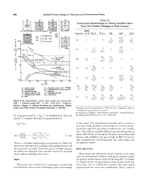
             Figure  5-19.  Characteristic  curves:  flow,  power,  and  mixing  time.   Q   Q          Q   p      Q
             (H/D  =  1, 8-blade paddle H/D  =  �.  d/D  =  1/10,  Hc,ID  =  �)  By  per-
             mission,  Nagata,  S.,  Mixing  Principles  and  Applications,  Halsted
                                                                                              3
             Press, John Wiley & Sons,  Kodasnsha Scientific.  p.  125 [34).   *Example:  Q/P  is  proportional  to  N({ /Np  on  a  comparison  basis  of
                                                                   keeping flow Q and speed N  constant.
                                                                  By  permission,  Oldshue,  "Fluid  Mixing Technology,"  Chemical Engineer-
             N,  is  proportional  to  l/N/13;  or  holding  flow  (Q)  and   ing,  McGraw-Hill Publications Co. Inc., 1983  [29].
             speed,  N,  constant then Q/P is proportional  to
                                                                   to  the vessel.  The manufacturers  usually take  a conserva-
                                                                   tive view of this  problem,  nevertheless it is well  to  under-
                                                                   stand the  expected operating conditions  for any installa-
                                                                   tion.  Normally an  impeller-shaft system should operate  at
                  (Q/P)1     (N   5/3'/N  3/4)  I                  about 40% of the critical speed. However,  the turbine with
                                     p
                              l  Q
             thus  ---                                    (5-40)
                                                                   bottom  side  stabilizer  can  go  as  high  as  80%  of critical.
                                                                   The  manufacturer  should  provide  this  information  for
             This  is  a valuable  relationship  as  expressed  in Table  5-2,   the specific system.
             because it expresses  the working relationship between all
             the important  variables. Note that as one variable changes   Drive and Gears
             all  others  are  changed.  One variable cannot be  changed
             alone without affecting the others.                     Most mixers  are  driven by electric  motors,  or in some
                                                                   cases  by  mechanical  turbines,  with  gears  ratioed  to  give
             Shaft                                                 the proper performance speed of the impeller.  A variable
                                                                   or  2-speed  driver or gear system  often  proves  worth  the
               The proper size of  shafi: is very important to avoid whip   extra  cost,  since  it is  difficult to  predict the  exact speed
             and vibration, destruction of bearings, gears,  and damage   requirements for some  new  installations.  This  is  particu-
   333   334   335   336   337   338   339   340   341   342   343