Page 337 - APPLIED PROCESS DESIGN FOR CHEMICAL AND PETROCHEMICAL PLANTS, Volume 1, 3rd Edition
P. 337

Mixing of Liquids                                       305


                  300  5             100           100,000
                      4.5            90
                      4              80      1,000
                  200   3.5
                      3              70      100
                                                                                        Turbine• Flat Bladt (6)
                      2.5            60                        -------------------  Turbine,Pilchtd  Bladt(6}
                                             10   _ ..  --  --
                      2                        .. -
                  100           ---- t-l     --
                   90  1.5_  --.     ��  -i
                   80           .. , .. ..   a.
                   70               ---  !  0.1
                   60  1.0                :z:        1,000                              2  Flat Paddles (O/W=6)
                                          0
                       .9            30
                   50
                     I  .8                                                              Proptller  Pitch =20
                   40.},  · 7                                                           Flat  Paddlt (0/W =41
                       .6                                                               Prapeller  Pitch= 0
                   30  0.5           20                                                 Flat Paddlt (O/W =6)
                                                     :100
                       .4           ..               ·o                                 Flat Paddle (O/W=Bl
                                                     a.
                   20               ..               ..
                      .. 3          .I::             c:                                 Flat Paddle(O/W=IO)
                                    <>
                                    -=               �
                                    �
                              l                      ..
                                                     :,,,.
                                                     ...
                                                     0
                 s     .2  •        l.,              .!!    �
                 a.
                 a::  IO   0.167; �                  >  10
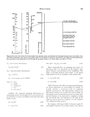
          Figure 5-18.  Laminar flow mixing.  For known impeller type, diameter,  speed, and viscosity,  this nomograph will give power consumption. Con-
          nect RPM  and diameter,  also viscosity and  impeller scale.  The intersection  of these two separate lines with  alpha and  beta respectively is
          then  connected to give horsepower on the HP scale.  By permission,  Quillen,  C.  S.,  Chem.  Engr.,  June 1954,  p.  177  (15].
          NQ  =  flow number,  dimensionless,                                                                 (5-37)
                                                         (5-2)     When  comparing  flow  (or  pumping)  per  power,  we
                                                                determine  that  it  is  dependent  on  the  impeller  type,
          '.\/Re  =  Reynolds number,  dimensionless            speed,  diameter,  and  geometry  of the  installation.  The
                                                                mixer  is  not  fully  specified  until  torque,  'C,  and  lateral
                                                         (5-7)   loads  (fluid force,  F)  are included in the analysis  [29].

             Nr =  force number,  '.'ir = F/  (PN D' 1)   (5-34)                                             (5-38)
                                      2
          when  M  =  mass                                                                                    (5-39)
                L  =  length
                T  =  temperature                                  Table 5-2 presents  the effects of  expected performance
                 t  =  time                                     on  various  parameters  or  relationships  for  mixing.  To
                F  =  force,  ML/t 2                            actually  calculate  a  numerical  result  of  comparing
                                                                impeller  performances,  the  dimensionless  numbers  for
                                                                flow  power and force are  needed.  Note  that in Table 5-2
             Oldshue  l29]  expresses  pumping  effectiveness  as
          pumping per power and recognizes it as a key function for   the constant basis is across the horizontal  top of the chart
          processes that are flow controlled or need more flow than   and  the  function to  be  examined  or  compared  is  along
          head  or shear.                                       the  vertical  left  side.  The  functions  in  the  body  of the
                                                                table  are  used  as  ratios  for condition  (1)  and  condition
                                                                (2), holding the basis constant,
                                                        (5-35)
                                                                   For example, referring to Table 5-2, if power input  (P)
                                                        (5-36)   and  impeller diameter,  D,  are  kept constant,  then speed,
   332   333   334   335   336   337   338   339   340   341   342