
Page 346 - APPLIED PROCESS DESIGN FOR CHEMICAL AND PETROCHEMICAL PLANTS, Volume 1, 3rd Edition
P. 346
314 Applied Process Design for Chemical and Petrochemical Plants
s.o \ ..___..___..,__ REACTION --+----t----+---+
FIRST-ORDER
8 v (I)
4.0
5 :z: 4
BATCH
2 i:
� 3.0 ... �
!z al
i:c 8 ls
0:
� o,: LL
z
ti 2.0 � �� 21-----1--+---1---1---+----+---''/
z
...
0 � ;:
u
co,n...,usl �
1.0 �
1--- 1L._--==::::::;:;;;;.===::�===::::;:;;�======��
0 0 20 40 60 80 100
TIME PERCENT REACTED
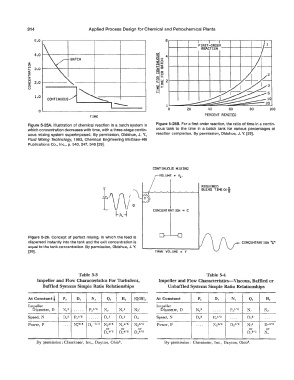
Figure 5-25A. Illustration of chemical reaction in a batch system in Figure 5-258. For a first order reaction, the ratio of time in a contin-
which concentration decreases with time, with a three-stage contin- uous tank to the time in a batch tank for various percentages of
uous mixing system superimposed. By permission, Oldshue, J. Y., reaction completion. By permission, Oldshue, J. Y. [29].
Fluid Mixing Technology, 1983, Chemical Engineering McGraw-Hill
Publications Co., Inc., p. 340, 347, 348 [29].
CONTINUOUS MIXING
VOLUME • Ve,
REQUIRED
,.._..,..._��---....------, BLEND TIHE0<}
CONCENTRATION= C
Figure 5-26. Concept of perfect mixing, in which the feed is �
dispersed instantly into the tank and the exit concentration is CONCENTRATION.-�
equal to the tank concentration. By permission, Oldshue, J. Y.
[29]. TANK VOLUME V
Table 5-3 Table 5-4
Impeller and Flow Characteristics For Turbulent, Impeller and Flow Characteristics-Viscous, Baffled or
Baffled Systems Simple Ratio Relationships Unbaffied Systems Simple Ratio Relationships
At Constant f P, D, N, Q, H, (Q/H), At Constant P, D, N, Q, H,
--- --- ---
Im ener Im eller
6 iameter, D N,a ..... p,11a N, N,2 N;I 6 iarneter, D N2 . ... p,112 N, N,
--- --- ---
r
Speed, N 0,6 p,115 ..... o,a 0,2 D, Speed, N 03 r,1,a . ... 03 . ...
r
r
--- --- ---
Power, P ... N;3t6 D -s;s N;•t6 N,416 N;:sto Power, P .... N;21a 0-312 N;t o-a12
r
'
or
or
or
or
or
D •ta o-•13 D s13 D a12 N,
r
r
r
t
By permission: Chemineer, Inc., Dayton, Ohio 8• By permission: Chemineer, Inc., Dayton, Ohio 8.