Page 343 - APPLIED PROCESS DESIGN FOR CHEMICAL AND PETROCHEMICAL PLANTS, Volume 1, 3rd Edition
P. 343

Mixing of Liquids                                       311


                                                                           Jet  from  Open  Pipe
                                                                        l=f��ai


                 Vortex
                                                                        -r- ::J =:;=:

                          Side  Viu,       Bottom  View                    Jet  from  Contracted   Jel from  Morine  Type
                                                                             Pipt or Nozzle
                                                                                                Propel!er
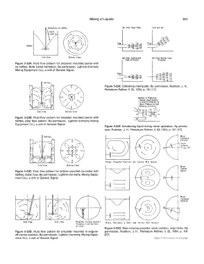
          Figure  5-23A.  Fluid  flow pattern  for propeller mounted  center with
          no baffles.  Note vortex formation.  By permission,  Lightnin (formerly
          Mixing Equipment Co.), a unit of General  Signal.             l
                                                                        p       "d-
                                                                        -i==!�=:,=l==

                                                                Figure 5-23E.  Entraining mixing jets.  By permission, Rushton, J. H.,
                                                                Petroleum Refiner,  V.  33,  1954,  p.  101  [17].

                                                                                    Method  A  Preferred
                                                                                      U nless  Liquid  Density
                                                                                  j  Cousing  Covitotion)
                                                                                      Greotly  Different er
                                                                                      opor Pressure  is  Hioh
                                                                                        ::::::::::  :::::_
                       Side  View       Bottom  View                                    -  -
                                                                                        _ Turbulent
                                                                                                -
                                                                                        - -.Core
          Figure  5-238.  Fluid  flow  pattern  for propeller mounted  center with   B   ;  ._  -
          baffles,  axial flow  pattern.  By permission,  Lightnin  (formerly Mixing
          Equipment Co.),  a unit of General  Signal.
                                                                Figure 5-23F.  Introducing  liquid during  mixer operation.  By permis-
                                                                sion,  Rushton, J. H., Petroleum Refiner,  V.  33,  1954,  p.  101  [17].


                                                                 Proper  Propeller  Position: No  Vortex  Will  Result
                        Side  View       Bottom View
                                                                                                              Mixer
                                                                                                              Clockwi
          Figure 5-23C.  Fluid flow pattern for turbine mounted on-center with                                Rotolil
          baffles,  radial flow.  By permission,  Lightnin (formerly,  Mixing Equip-
          ment Co.), a unit of General Signal.


                                                                                                              Mixer
                                                                                                              Clockwise
                                                                                                              Rotation


               Side  View         Side  View   Propeller  Turning  Counter·   Wrono  Positions: A  Swirl  ond  Vortex  Will  Result
                                               Clockwise  Looking  Down
                                               on  Sha:t
                                                                Figure 5-23G. Side-entering propeller mixer position, large tanks. By
          Figure  5-230.  Fluid  flow  pattern  for propeller mounted  in  angular-   permission,  Rushton,  J.  H.,  Petroleum  Refiner,  V.  33,  1954,  p.  101
          off-center position.  By permission,  Lightnin (formerly,  Mixing Equip-   [17].
          ment Co.),  a unit of General Signal.                                               (Figure  5-2) continued  Oil next page)
   338   339   340   341   342   343   344   345   346   347   348