
Page 347 - APPLIED PROCESS DESIGN FOR CHEMICAL AND PETROCHEMICAL PLANTS, Volume 1, 3rd Edition
P. 347
Mixing of Liquids 315
3 and 5-4 present the relationships of the major variables the two variables can be established. The third variable is
for the two most important cases of mixing. tied through the power curves (plot of power number v.
NRe• see Figures 5-13, 5-14, and 5-15). Figure 5-28 shows
Often, exact or true kinematic and dynamic similarity that geometric and dynamic similarity can develop useful
cannot be achieved in a system requiring small scale test- relationships for some situations [29], but not all, and it is
ing to determine the effect of the design, or flexibility in not truly possible to prepare one dimensionless group
design to allow for final design "trimming." Consideration expressing a process relationship. This suggests that care
should definitely be given to such flexibility as (a) mixing must be used in resorting only to a dimensionless number
impeller designs that can be modified without excessive for process correlations. Also see Figures 5-29 and 5-30.
cost, or the need to build a completely new/larger/small- Because the most common impeller type is the turbine,
er unit, (b) multiple gear ratios for the gear drive, with most scale-up published studies have been devoted to that
spare ratio gears to adjust speeds, and (c) either variable unit. Almost all scale-up situations require duplication of
speed driver or oversized driver to allow for horsepower process results from the initial scale to the second scaled
adjustments. unit. Therefore, this is the objective of the outline to fol-
The dynamic response used to describe fluid motion in low, from Reference [32]. The dynamic response is used
the system is bulk velocity. Kinematic similarity exists with as a reference for agitation/mixer behavior for a defined
geometric similarity in turbulent agitation [32]. To dupli- set of process results. For turbulent mixing, kinematic
cate a velocity in the kinernatically similar system, the similarity occurs with geometric similarity, meaning fixed
known velocity must be held constant, for example, the ratios exist between corresponding velocities.
velocity of the tip speed of the impeller must be constant. For scale-up procedure, refer to Figure 5-31, which out-
Ultimately, the process result should be duplicated in the lines the steps involved in selecting commercial or industri-
scaled-up design. Therefore, the geometric similarity goes al mechanical agitation equipment when based on test data.
a long way in achieving this for some processes, and the
achievement of dynamic and/or kinematic similarity is • Test data should be planned by knowledgeable special-
sometimes not that essential. ists in order to obtain the range, accuracy, and scope of
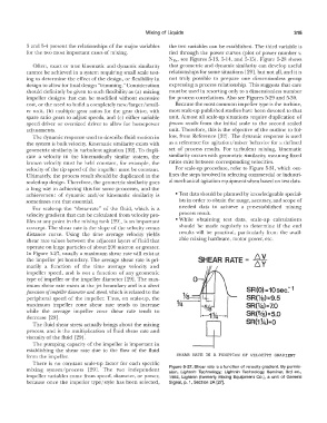
For scale-up the "shear-rate" of the fluid, which is a needed data to achieve a pre-established mixing
velocity gradient that. can be calculated from velocity pro- process result.
files at any point in the mixing tank [29], is an important • While obtaining test data, scale-up calculations
concept. The shear rate is the slope of the velocity versus should be made regularly to determine if the end
distance curve. Using the time average velocity yields results will be practical, particuiarly from the avail-
shear rate vaiues between the adjacent layers of fluid that able mixing hardware, motor power, etc.
operate on large particles of about 200 micron or greater.
In Figure 5-27, usually a maximum shear rate will exist at
the impeller jet boundary. The average shear rate is pri- SHEAR RATE = b.. V
b..Y
marily a function of the time average velocity and
impeller speed, and is not a function of any geometric
type of impeller or the impeller diameter [29]. The max-
imum shear rate exists at the jet boundary and is a direct
function of impeller diameter and speed, which is related to the SR (0) = 10 sec: 1
peripheral speed of the impeller. Thus, on scale-up, the SR(Va)=9.5
maximum impeller zone shear rate tends to increase SR(1/4)= 7.0
while the average impeller zone shear rate tends to SR(S/a)=S.O
decrease [29].
The fluid shear stress actually brings about the mixing SR(1°Ui)=O
process, and is the multipiication of fluid shear rate and
viscosity of the fluid [29].
The pumping capacity of the impeller is important in
establishing the shear rate due to the flow of the fluid
from the impeller. SHEAR RATE IS A FUNCTION OF VELOCITY GRADI�NT
There is no constant scale-up factor for each specific
mixing system/process [29J. The two independent Figure 5-27. Shear rate is a function of velocity gradient. By permis-
sion, Lightnin Technology; Lightnin Technology Seminar, 3rd ed.,
impeller variables come from speed, diameter, or power, 1982, Lightnin (formerly Mixing Equipment Co.), a unit of General
because once the impeller type/style has been selected, Signal, p. 1, Section 2A [27].