Page 348 - APPLIED PROCESS DESIGN FOR CHEMICAL AND PETROCHEMICAL PLANTS, Volume 1, 3rd Edition
P. 348

316                       Applied Process Design for Chemical and Petrochemical  Plants

           100
                             Equal heat transfer                       0 • IMPEUER  DIAMETER
                             per unit volume - L,..,,-   I/            T•TANK DIAMETER  (Co.lSTANT)
                                      I/        v  v               20  IMPELLER  TYPE  CONSTANT----.11�---+-�
                                    1/
                            v           1,/   time-T                101--��i---�t---+.,..,....-i�- �- �-+--+-1
                T• Turbulent flow
             -                   v          �qualblend
                L• Laminar flow
                                                                                                     ......
                                                                                               ......
           10                    -  -   !,,  .....                  8t--��+-��-+--7''+---+--+--.  .......  �+-.,,,-.�+-�+--+--t
                                -                                   61--����.....,C.-+-�+-'1""+-�-.,.c+-��-+-�+--+--t
         �              ./   ./                                  (/)
         �            v                                          (/)   4t--��'4-��-4-.  .......  -+---+  ........  ;.._��+-��-+-�-+--+--t
                    v  ...          Equal N r,  .  er equal heat 1ransfer coetficient   uJ
                                                                 (.)
         �                          on i"ti•ivl 'i"['•:.::.+--+-t-tr   i
         �        v  v""         -                               a.
         i   g  ...... ..... -  ... -   ..---   ........--r  II  I  I  I   I   I   I   I  I
                  ,,/'
         .ii      ,...--            /  - Equal bubble and drop diameter  - T
                                    ,..-Equal  heat transfer coefficient - L
         £  1.0                   «'.   ...   .u
         l    ' - - ......   �      .. Equal mass  and heat transfer coefficient:   1...._��"--��.1--......1.�1......J'-----'��--'�  .......  ��
                                     Equal blend time
                                               L
               '\.  ....
         l      '\.  "\.   .......   "'-   ....   -  �   particles bubbles,  drops  T   QI   Q2   0.4  0.6   I   2   4   6   10
                                                     I
                                                      I  I  I
                                                I
                                                   I
                                                                                    HORSEPOWER
         0        I\.   -- .....   .........   -,....   "1-N
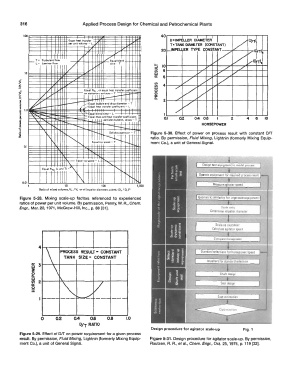
         .2        \      '�                  Solids suspension - T   Figure  5-30.  Effect  of  power  on  process  result  with  constant  D/T
         l           \       <,            .  "'±-.            ratio.  By permission,  Fluid Mixing,  Lightnin  (formerly Mixing  Equip-
                      [\         <,    Equal  tip speed·- T   r--.  ........   ment Co.), a unit of General Signal.
           0.1
                                            .....
                                Equal  11p speed - L
                             \.              <,                                     Oitiign  test equipment to  mo<al  proceu
                              �                 <,
                  Equal  NR•  (land T)  ....
                           11  I\                    .........  .... �             Operate equrpmanT  for r&q�irod  prrn:..u ruult
          0.01
             1              10             100           1,000
                 Ratio of mixed volumes, V 2  I V 1  or of impeller diameters cubed, (0 1  I 0 1)  1
         Figure  5-28.  Mixing  scale-up  factors  referenced  to  experienced     Geomeiric �imilerity  for  larfl(! scale equipment
         ratios of power per unit volume.  By permission,  Penny,  W.  A., Chem.
         Engr.,  Mar.  22,  1971, McGraw-Hill, Inc.,  p. 88 [31].                           S�le ratio
                                                                                        Determine imp�lier drameler
                                                                                          Scwle-up upononr
                                                                                        Calcula1e agitator spee�
                                                                                         Compu!e ho""po,..,,
                                                                                    Standard sstect.nns forhor�power/speed
                                                                                      lmpellerl lor standard ,election


                                                                                            Shalt desrgn
                                                                                            Sear desrgn


                                                                                           Cost estimation


                  0     Q2     0.4    0.8    0.8     1.0
                                  D/T  RATIO
                                                               Design procedure  for agitator scale-up   Fig.  1
         Figure 5-29. Effect of Off on power requirement for a given process
         result.  By permission, Fluid Mixing,  Lightnin (formerly Mixing Equip-   Figure 5-31. Design procedure for agitator scale-up.  By permission,
         ment Co.), a unit of General Signal.                  Rautzen,  A.  A., et al.,  Chem.  Engr.,  Oct.  25,  1976,  p.  119 [32].
   343   344   345   346   347   348   349   350   351   352   353