
Page 352 - APPLIED PROCESS DESIGN FOR CHEMICAL AND PETROCHEMICAL PLANTS, Volume 1, 3rd Edition
P. 352
320 Applied Process Design for Chemical and Petrochemical Plants
cl
bw
z
cl Cone tie-in
For very low to shell
impellers, add
1 /2 width baffles
in cone, off wall
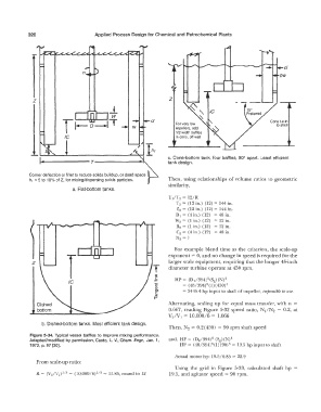
c. Cone-bottom tank, four baffles, 90° apart. Least efficient
tank design.
Corner deflection or fillet to reduce solids buildup, or dead space
h 1 = 5 to 10% of Z, for mixing/dispersing solids particles. Then, using relationships of volume ratios to geometric
similarity,
a. Flat-bottom tanks.
T1/T 2 = 12/R
T 2 = (12 in.) (12) = 144 in.
Z2 = (12 in.) (12) = 144 in.
D1 = (4 in.) (12) = 48 in.
W 2 = (1 in.) (12) = 12 in.
B2 = (1 in.) (12) = 12 in.
C2 = (4 in.) (12) = 48 in.
N2 =?
For example blend time as the criterion, the scale-up
exponent= 0, and no change in speed is required for the
z larger scale equipment, requiring that the longer 48-inch
diameter turbine operate at 450 rpm,
Cl)
§ HP = (DT/394)5(Scr) (N)3
c = (48/391) 5 (1)°(450)3
Cl)
Ol = 2445.4 hp input to shaft of impeller, impossible to use.
c
�
Dished Alternating, scaling up for equal mass transfer, with n =
bottom 0.667, reading Figure 5-32 speed ratio, N1/N2 = 0.2, at
V2/V 1 = 10,000/6 = 1,666
b. Dished-bottom tanks. Most efficient tank design.
Then, N2 = 0.2(450) = 90 rpm shaft speed
Figure 5-34. Typical vessel baffles to improve mixing performance.
Adapted/modified by permission, Casto, L. V., Chem. Engr., Jan. 1, and, HP= (0 2 /394)5 (Sg) (N)3
5
3
1972, p. 97 [30]. HP= (48/391) (1)(90) = 19.5 hp input to shaft
Acural motor hp: 19.5/0.85 == 22.9
From scale-up ratio:
Using the grid in Figure 5-33, calculated shaft hp
2
R = (V /V 1)113 = (10,000/6) 113 = 11.85, round to 12 19.5, and agitator speed = 90 rpm.