
Page 356 - APPLIED PROCESS DESIGN FOR CHEMICAL AND PETROCHEMICAL PLANTS, Volume 1, 3rd Edition
P. 356
324 Applied Process Design for Chemical and Petrochemical Plants
10 For side entering horizontal mixers not limited to
- blending operations, there are some differences in rec-
__.......- ommendations concerning the physical location of the
SJI �� 0.4 impeller:
........ - ,.,........ B
� ........... .I 1. The impeller should be located � to rn times the
vv impeller diameter away from the tank wall in plan.
n fl u c
2. The impeller centerline should be � to 20 off the
tank bottom.
I 10
0.1 1.0
PO Hr 3. The impeller shaft should make a plan angle of 8°
to 30° (10° optimum) to the left of a centerline of
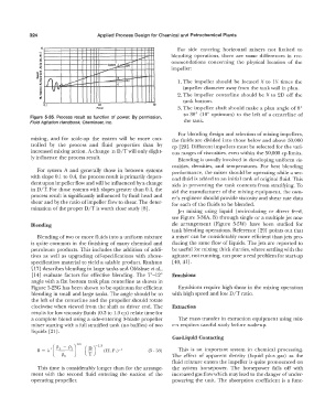
Figure 5-35. Process result as function of power. By permission,
Fluid Agitation Handbook, Chemineer, Inc. the tank.
For blending design and selection of mixing impellers,
m1xmg, and for scale-up the system will be more con- the fluids are divided into those below and above 50,000
trolled by the process and fluid properties than by cp [29). Different impellers must be selected for the vari-
increased mixing action. A change in D/T will only slight- ous ranges of viscosities, even within the 50,000 cp limits.
ly influence the process result. Blending is usually involved in developing uniform vis-
cosities, densities, and temperatures. For best blending
For system A and generally those in between systems performance, the mixer should be operating while a sec-
with slope 0.1 to 0.4, the process result is primarily depen- ond fluid is added to an initial tank of original fluid. This
dent upon impeller flow and will be influenced by a change aids in preventing the tank contents from stratifying. To
in D/T. For those systems with slopes greater than 0.4, the aid the manufacturer of the mixing equipment, the own-
process result is significantly influenced by fluid head and er's engineer should provide viscosity and shear rate data
shear and by the ratio of impeller flow to shear. The deter- for each of the fluids to be blended.
mination of the proper D/T is worth close study [8].
Jet mixing using liquid (recirculating or direct feed,
see Figure 5-36A, B) through single or a multiple jet noz-
Blending zle arrangement (Figure 5-5W) have been studied for
tank blending operations. Reference [29) points out that
Blending of two or more fluids into a uniform mixture a mixer can be considerably more efficient than jets pro-
is quite common in the finishing of many chemical and ducing the same flow of liquids. The jets are reported to
petroleum products. This includes the addition of addi- be useful for mixing thick slurries, where settling with the
tives as well as upgrading off-specifications with above- agitator, not running, can pose a real problem for start-up
specification material to yield a salable product. Rushton [40, 41].
[17) describes blending in large tanks and Oldshue et al.,
[14] evaluate factors for effective blending. The 7°-12° Emulsions
angle with a flat bottom tank plan centerline as shown in
Figure 5-23G has been shown to be optimum for efficient Emulsions require high shear in the mixing operation
blending in small and large tanks. The angle should be to with high speed and low D/T ratio.
the left of the centerline and the propeller should rotate
clockwise when viewed from the shaft or driver end. The Extraction
results for low viscosity fluids (0.3 to 1.0 cp) relate time for
a complete blend using a side-entering 3-blade propeller The mass transfer in extraction equipment using mix-
mixer starting with a full stratified tank (no baffles) of two ers requires careful study before scale-up.
liquids [21].
Gas-Liquid Contacting
(5 - 68) This is an important system in chemical processing.
The effect of apparent density (liquid plus gas) as the
fluid mixture enters the impeller is quite pronounced on
This time is considerably longer than for the arrange- the system horsepower. The horsepower falls off with
ment with the second fluid entering the suction of the increased gas flow which may lead to the danger ofunder-
operating propeller. powering the unit. The absorption coefficient is a func-