
Page 357 - APPLIED PROCESS DESIGN FOR CHEMICAL AND PETROCHEMICAL PLANTS, Volume 1, 3rd Edition
P. 357
Mixing of Liquids 325
PRESSURE CONNECTION PRESSURE CONNECTION
DISCHARGE.
Can be
thrHded
or pl1in.
REMOVABLE
NOZZLE
SUCTION
CONNECTION REMOVABLE
THROAT
SUCTION PIECE
REMOVABLE CONNECTION
NOZZLE
SUCTION SUCTIOfl
LIQUID LIQUID
FLOW FLOW
PRESSURE CONNECTION
DISCHARGE DISCHARGE
CONNECTION CONNECTION
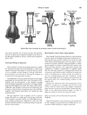
Figure 5-36A. Liquid mixing jets. By permission, Ketema, Schutte and Koerting Div.
tion of the impeller size, its speed and the inlet gas flow Heat Transfer: Coils in Tank, Liquid Agitated
rate. For scale-up they should be handled in the form of
the Sherwood number k 1 (D/Dv), which can be related to Heat transfer during mixing of fluids in a tank depends
power [21]. to some extent on the degree of mixing, turbulence, etc.,
affecting the heat transfer coefficient 011 the process side
of the system and flowing against the coils, plates, or other
Gas-Liquid Mixing or Dispersion surfaces for transfer. However, sizing an impeller or select-
ing an impeller to achieve a particular heat transfer coef-
This is another common processing operation, usually ficient has been proven to be impractical, because the
for chemical reactions and neutralizations or other mass coefficient is relatively independent of impeller speed
transfer functions. Pilot plant or research data are.need- [29, 35]. The heat transfer in a mixing vessel is by forced
ed to accomplish a proper design or scale-up. Therefore, connection, and its heat transfer coefficient is usually one
generalizations can only assist in alerting the designer as of the controlling factors to heat transfer. The other fac-
to what type of mixing system to expect. tors are cooling/heating side film coefficient, except
when condensing steam, the scaling or fouling factors on
This dispersion of the gas passes through several stages the process side, and coolant/heating medium on the
depending on the gas feed rate to the underside of the opposite side.
impeller and the horsepower to the impeller, varying
from inadequate dispersion at low flow to total gas bubble Despite the technical study and examination of this
dispersion throughout the vessel. The open, without disk, subject, it is important to recognize that because of the
radial flow type impeller is the preferred dispersing unit variety of factors noted earlier, the designer should not
because it requires lower horsepower than the axial flow expect precise results and should allow considerable flex-
impeller. The impeller determines the bubble size and ibility in the physical/mechanical design in order to
interfacial area. adjust the system to achieve the required results.
The gas dispersion ring or sparger can be a special Effects of viscosity on Process Fluid Heat Transfer Film
design with holes or a single pipe entering the underside Coefficient
of the impeller, and there will be very little differences in
mass transfer performance. References [25] and [29] Figure 5-37 presents a typical heating and cooling chart
provide valuable detail for considering design for gas dis- for the changes in process side film coefficients, h 0, as a
persion/mass transfer. function of bulk viscosity for organic chemicals.